| Module | Name | Version | License | Source | Languages | Platforms | Type | Author | Description |
|---|---|---|---|---|---|---|---|---|---|
| WebCfg | Program configurator (WEB) | 1.7 | GPL2 | ui_WebCfg.so | en,uk,ru,de | x86,x86_64,ARM | UI | Roman Savochenko Maxim Lysenko (2009) — the page translation |
Provides the WEB-based configurator of OpenSCADA. |
Contents
The "WebCfg" module provides a configurator of OpenSCADA. Configurator is based on Web-technologies. For configurator working it is enough the usual WEB-Browser. The operability of the module "WebCfg" was tested in conjunction with modules "Transport.Sockets" and "Protocol.HTTP" on the following Web-browsers:
- Mozilla;
- Firefox;
- Konqueror;
- Opera;
- IE.
The module is based on the language of OpenSCADA control, and thus provides a uniform configuration interface. Updating of the module may be required only in the case of updating the specification of the control language.
In addition to the belonging of the module to OpenSCADA, it also belongs, is a module, to the transport protocol module "HTTP". Actually, the call "WebCfg" makes from "HTTP" and through enhanced communication mechanism, through exported in the module "WebCfg" features: HttpGet() and HttpSet().
The interface of the module is implemented by means of the language XHTML 1.0 Transitional with inclusions of the JavaScript.
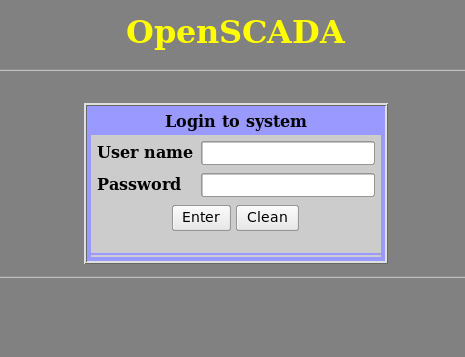
Using the module starts with the opening session, the user authentication of the user module by the protocol HTTP (Protocol.HTTP) (Fig. 1). For the operation of the authentication and session saving mechanism the browser must allow Cookies.
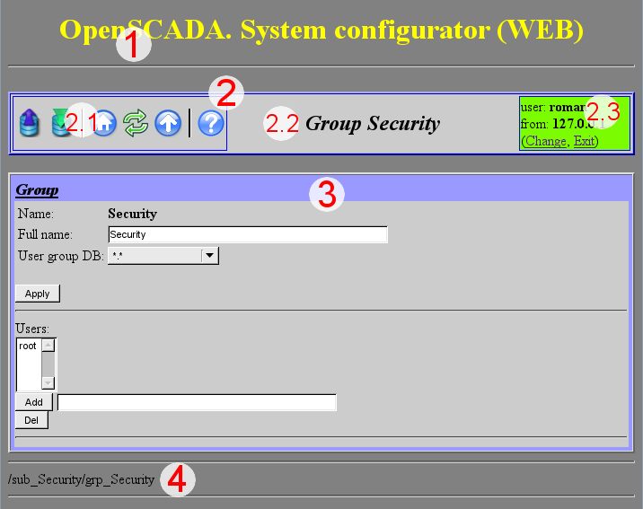
After authenticating the user enters the operating window (Fig.2), which consists of the following parts:
- 1. Header — contains the name of the module.
- 2. Control Panel — consists of:
- 2.1. Navigator — serves the navigation functions throug the tree of pages.
- 2.2. The name of the node.
- 2.3. User of the System — Displays the current user of the session, his address and lets you to change the user.
- 3. Workplace field — contains the configuration settings of language of management interface, starting with the root tabs to the end elements.
- 4. Footer — contains the address of current page.
Addressing of the pages begins with an element of second-level URL. This is due to the fact that the first-level element is used to identify the module of user Web-interface. For example URL: "http://localhost.localdomain:10002/WebCfg//Functions" can be deciphered as call of the first-level page "Functions" of the Web module "WebCfg" on the host localhost.localdomain through the port 10002.
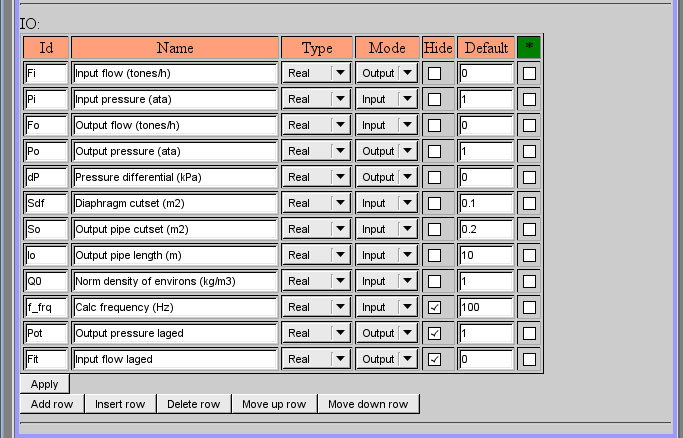
The control tools are divided into: basic, commands, lists, tables and images. All four types are displayed by individual units not depending on their location in the description.
1 Basic elements
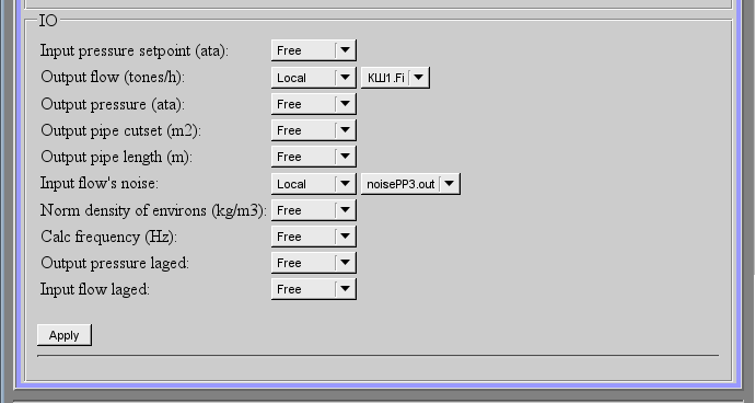
The basic elements include: information elements, the field for input of the values, the elements of combo box, flags. To set the new values of the basic elements the group method is used, for this there is a button "Accept" on the form. In the case of the absence of an element name, the basic element connects to the previous one. Examples of basic elements, with connections, is shown in Figure 3.
2 Commands
Commands are the elements for the transfer of the certain instructions of the action to the node and for the organization of the links on the page. Commands may contain parameters. The parameters are formed from the basic elements. Example of the commands with the parameters is shown in Figure 4.
3 Lists
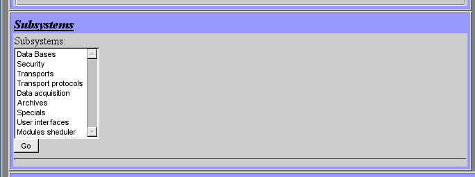
Lists contain a group of basic elements of the same type. For operations on elements of a list the additional buttons are added. In addition, through the elements of a list the moving operations to other pages are carried out. To move the button "Go" is added. Lists can be indexed. Example of the list with the moving is shown in Figure 5.
4 Tables
The tables contain values of basic elements. Type of the basic element is defined separately for each column. Example of the table is shown in Figure 6.
5 Images
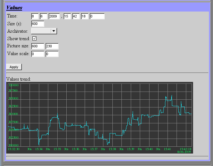
The images are designed to transmit graphic information into the configurators. Example of the image is shown in Figure 7.
