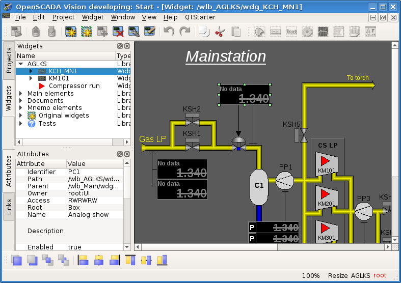
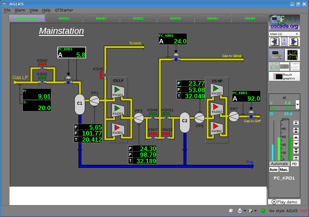
Author: Roman Savochenko, Maxim Lysenko (2010-2012)
Contents
- 1 Terms, definitions and abbreviations
- 2 OpenSCADA installation
- 3 Initial configuration and start up
- 4 Working with data sources
- 5 Formation of the visual representation
- 6 Conclusion
- 7 Links
OpenSCADA is an extremely modular, flexible and multifunctional SCADA system. As a result, the first acquaintance with OpenSCADA can be quite complicated, due to the small chances of matching the previous experience of the user, or its complete absence, with the approaches of work in OpenSCADA. However, in large part, this is only the first impression, since all OpenSCADA power is in the hands of the user and from the variety of which the user may be confused, and it may require considerable effort to select the functions needed to solve its task.
For this reason, this document was created for a clear presentation of the general concept of work in OpenSCADA. The document, on examples and in a relatively short and visual form, provides a way from installation and startup OpenSCADA up to creating user interface elements. The "Frequently Asked Questions" and "How to ..." documents can be used as a targeted help in the configuration, implementation and solving typical tasks around OpenSCADA.
The document is intended for OpenSCADA version 0.9 and greater. If you are interested in this document for earlier versions then you can get it from the documentation that goes with the packages with that version of OpenSCADA, or from old Wiki document.
The document does not contain a detailed description of the concept and deepening to the OpenSCADA detail, but provides links to documents that contain such information, and in the first place that is "Program manual".
The document is built synchronously with the examples implementation connected to the demo database (DB), the simulator "AGLKS", as a data source — PLC. Accordingly, the user must receive the OpenSCADA distribution with this DB, as described in more detail in the part "Installation"!
1 Terms, definitions and abbreviations
1.1 Terms and definitions
- Blocking — a conditional border of the technological parameter value at which overcome there performs a preset algorithm for the emergency prevent. In some modes of TP (starting) according to the regulations you can be needed for the blockings disable — deblocking.
- Deblocking — the process of the blockings disabling on time of TP working in modes for which the operation reserved into the regulations. The technological parameters deblocking is strictly accountable operation and it must be performed by the operative personal in an appropriate order!
- Complex parameter-tag or object-tag of the signal — detailed signal of the data source as a complex parameter-tag, which for analog one usually contains:
- signal value in the engineering-real measurement unit;
- name of the measurement unit;
- scale-range of the signal value physical changing - minimum and maximum borders;
- signaling scale borders — usually the upper and lower boundaries for warning and alarms;
- filter parameters;
- parameters of the scale specifics, determining the authenticity, format of presentation and more.
- Data model — organization and structuring of the technological process (TP) data or other automation object in the layer of SCADA data source, protocol or PLC. By default, this means OpenSCADA data source layer with the structure "Controller object" -> "Parameter, Level 1" -> ... "Parameter, Level N" -> "Attribute of value - signal".
- Project — this term has many meanings and, depending on the context, may be implied:
- OpenSCADA project (program) — free software, the documentation of which you are reading now.
- Specified set-folder of the configuration and data that are created by the user of OpenSCADA, where the configuration is stored in the configuration file (required) and one or more DB files (optionally and maybe online). For example — a demonstration project, simulator of the TP "AGLKS". That is, the author of the project is the user of the program — the engineer-developer or programmer of the SCADA system.
- VCA project — a component of the visualization control area (VCA) created in the module UI.VCAEngine through UI.Vision and contains a set of VCA frames.
- Qt — software development tool, with which, in particular, the QTStarter (starter of OpenSCADA modules on the library Qt), QTCfg (GUI configurator of OpenSCADA) and Vision (editor and executant of the working user interfaces of VCA) modules are created. It may be encountered in the form of QT, which is an early entry used by OpenSCADA developers for the Qt library.
- Quietance — approving process is a fact of the operative personal take its attention to the violation into the TP work. The process mostly means of take actions for the violation eliminating and pressing to the button of the alarm quieting.
- Setting of the alarm — a conditional border of the technological parameter value at which overcome means as an abnormal situation. Typically there set next borders:
- Upper and bottom alarm borders — borders of alarm values of the technological parameter.
- Upper and bottom warning borders — borders of warning, the regulations borders, about the parameter value exit beyond the work range.
- Failure — points to the parameter value out of hardware borders of the technological equipment. That is mostly features to the sensor failure, break of the channel link with the sensor or the PLC.
- Signal (in relation to the data source) — element of the data source in the form of measured, or calculated, value of the technological parameter or sensor. Represents a scalar of a discrete, integer or real type, which is often encoded, by scaling the parameter scale to the integer dimension. The signal, for identification, is often simply indexed or encoded at the address of its value on the map of the exchanging protocol, and the meaningful name appears in the SCADA data model.
- Signaling — the process of notification of the operative personal about a violation of the technological process or the automation equipment work. The notification methods can be at different types of influence to the human senses for take it attention. There often provides next types of signaling:
- Light signaling — that is typically performed by changing color of the graphical object (blink) for the emerging events and by setting the static alarm colors (red and yellow) for events have quietance-confirmation.
- Sound — that is performed by sound signal out in moment of the event emerge. The sound signal type can be both as monotonic and the speech synth message with an information about the violation.
- VCA frame — derived visualization element, consisting of the basic elements and able to serve functions of the project page of VCA.
- VCA widget — visualization element of the VCA.
1.2 Used abbreviations
- API — Application Programming Interface (OpenSCADA modules) or extensions in the internal language of OpenSCADA — User API.
- AWP — Automated Work Place. Usually it is a system unit of a computer system, a display, a mouse "manipulator", sometimes with a keyboard, and other peripheral equipment, which serves to visualize the data of the technological process, as well as the issuance of control actions on the TP.
- DAQ — Data Acquisition.
- DB — Database.
- DCON — the name of one of the communication protocols used in the industry.
- FS — filesystem.
- GPL — General Public License, under the conditions of which OpenSCADA may be distributed and used.
- GUI — Graphical User Interface.
- HMI — Human-Machine Interface.
- HTTP — HyperText Transfer Protocol.
- MOD — Matching to Object Device. Number of devices or PLC modules to whose being directly connected signals from sensors of the TP for followed converting from analog to digital form and back. The conversion performs with a point of following processing of the technological parameters into PLC.
- ModBus — Modicon BUS is a serial communications protocol, in the variants RTU and ASCII, originally published by Modicon in 1979 for use with its PLCs. Later it was expanded to work over TCP-IP and this variant was named ModBus/TCP.
- PLC — Programmable Logic Controller.
- QT — look for QT in the list of terms, it is not acronym.
- SCADA — Supervisory Control and Data Acquisition.
- SO — Signal Object.
- TP — Technological Process. Whole complex of technological equipment of the technological process.
- TUI — Terminal(Text) User Interface.
- UI — User Interface.
- VCA — Visual Control Area.
2 OpenSCADA installation
Installing OpenSCADA, in general, can be done in two ways. The first and simplest way is to get ready-made packages for the Linux distribution that you are using. The second is to compile OpenSCADA from the source code.
The installation procedure is highly dependent on the Linux distribution you are using and it is not possible to describe it exhaustively in this manual. Therefore, you may need to get a deep knowledge of the mechanisms of installing the software of the selected Linux distribution from its documentation. In the event that the user does not have such knowledge, skills and preferences for a Linux distribution, it is advisable to choose it according to the availability of OpenSCADA packages, which provides the simplest and most trouble free installation.
If the user is having trouble installing not only OpenSCADA, but also the Linux distribution, then for the first time, he can use the "live" Linux distribution with installed and ready to work and studying the demonstration and full-featured OpenSCADA. If this environment of rapid availability is suited for you then you can stop on it and install it. At this time, "live" builds based on the Debian and ALTLinux (deprecated) distributions are available as hybrid CD/DVD/USB stamps, at the page: http://oscada.org/en/main/download/. For more information, see the "How to ..." document "Live disk CD/DVD/USB".
2.1 Install OpenSCADA from ready-made packages
Installing from the ready-made packages, in turn, can be done in two ways. The first one is simpler when OpenSCADA packages are already present in their own OpenSCADA package repositories or the official, additional repositories of the used Linux distribution. Installing these packages is a matter of running a typical distribution package management program with the subsequent selection of OpenSCADA packages. In addition to simple installation, the package repository generally allows you to simply keep the operating system updated, safe and up to date! The second method involves obtaining and installing OpenSCADA packages manually.
You can check the availability of OpenSCADA packages in the repositories of Linux distributions or OpenSCADA, as well as download OpenSCADA packages for manual installation, on the download page of the official OpenSCADA site (http://oscada.org/en/main/download/). Here you can also get the configuration for connecting the OpenSCADA package repositories to the package manager of your Linux distribution.
![]() You must download packages and connect packages repositories directly to the version of the distribution that you use, otherwise there may be unresolved dependency problems at the installation process.
You must download packages and connect packages repositories directly to the version of the distribution that you use, otherwise there may be unresolved dependency problems at the installation process.
2.1.1 Adding a package repository and installing OpenSCADA from it
Package repositories are provided by the OpenSCADA project, whose service information is usually located along with the packages themselves and is updated automatically at the building, that is, these repositories are most up-to-date and preferable. Although OpenSCADA packages can still be found in the repositories of such Linux distributions: ALTLinux and distributions based on the package base Fedora, but they are there, rather will be old ones, since the packages building to the distribution repositories from the developers is not practiced right now!
Repository addresses and configurations for the repository manager can be found on the same OpenSCADA download page (http://oscada.org/en/main/download/) or in the examples below.
When installing from the repository, we select only the package with the configuration of the OpenSCADA project or the model. Everything else, according to the dependencies, will be selected and installed automatically. The following packages of this kind are usually provided:
- openscada-model-aglks, openscada-model-boiler — projects of dynamic simulators of technological processes, which together perform the function of demonstrating OpenSCADA;
- openscada-vis-station — a template project of the SCADA station, usually run in a graphical interface and without a Web;
- openscada-server — template project of the SCADA server, running in the background — the daemon mode;
- openscada-plc — PLC template project, running in the background — the daemon mode;
- openscada — typical-complete installation of OpenSCADA.
Installation-update from the repository is simple but specific to the Linux distribution, window manager or a separate program for working with repositories and packages, so we will send the reader to the appropriate documentation for the distribution or program that it uses. Here's a brief look at adding a repository and installing OpenSCADA with standard command line tools:
Packages repositories based on the package manager APT (Debian, Ubuntu, ALTLinux) — are added by the location of the downloaded file "openscada.list" to the /etc/apt/sources.list.d folder or by editing the /etc/apt/sources.list file by inserting one line:
Debian: "deb http://ftp.oscada.org/OpenSCADA/0.9.0/Debian/9 ./"
Debian (Work version): "deb http://ftp.oscada.org/OpenSCADA/Work/Debian/9 ./"
Debian (Work version, modules separated): "deb http://ftp.oscada.org/Debian/9/openscada ./"
Ubuntu: "deb http://ftp.oscada.org/OpenSCADA/0.9.0/Ubuntu/16.04 ./"
Ubuntu (Work version): "deb http://ftp.oscada.org/OpenSCADA/Work/Ubuntu/16.04 ./"
Installing:
$ apt-get update
$ apt-get install openscada-model-aglks
ALTLinux: "rpm http://ftp.oscada.org/OpenSCADA/0.9.0/ALTLinux/7 openscada main"
ALTLinux (Work version): "rpm http://ftp.oscada.org/OpenSCADA/Work/ALTLinux/6 openscada main"
ALTLinux (Work version, modules separated): "rpm http://ftp.oscada.org/ALTLinux/7 openscada main"
Installing:
$ apt-get update
$ apt-get install openscada-Model.AGLKS
Adding the signature verification key (the authenticity) of the repository and packages in it (not necessarily and not in all repositories):
$ wget -O - http://ftp.oscada.org/Misc/pkgSignKey | sudo apt-key add -
Packages repositories based on the package manager YUM (RedHat, Fedora, CentOs) — are added by uploading or creating a file /etc/yum.repos.d/openscada.repo with the contents:
[openscada]
name=OpenSCADA
#CentoOs
baseurl=http://ftp.oscada.org/OpenSCADA/0.9.0/CentOs/7
#CentoOs (Work version)
#baseurl=http://ftp.oscada.org/OpenSCADA/Work/CentOs/6
#Fedora (Work version)
#baseurl=http://ftp.oscada.org/OpenSCADA/Work/Fedora/12
enabled=1
gpgcheck=0
Installing:
$ yum install openscada-Model.AGLKS
The packages repositories SuSE YaST — are added by the command:
$ zypper ar -f http://ftp.oscada.org/OpenSCADA/0.9.0/SuSE/13 OpenSCADA
Installing:
$ zypper in openscada-Model.AGLKS
2.1.2 Manual installation of the OpenSCADA packages
To manually install the OpenSCADA packages, you need to download them from the official site or another source. You can usually download two sets of the packages.
The first set is represented by eleventh packages:
- openscada — package with all the files needed to launch OpenSCADA in full volume, including all modules;
- openscada-server — contains dependencies, a script file and a server project configuration to run OpenSCADA in the daemon-service mode;
- openscada-libdb-main — the main OpenSCADA libraries for data acquisition and other, in the SQLite database;
- openscada-libdb-vca — visual component libraries in the SQLite database;
- openscada-model-aglks — DB and the configuration of the dynamic real-time model "AGLKS" (Demo: EN,UK,RU);
- openscada-model-boiler — DB and the configuration of the dynamic real-time model "Boiler" (EN,UK,RU);
- openscada-doc-en — offline documentation of OpenSCADA, English;
- openscada-doc-uk — offline documentation of OpenSCADA, Ukrainian;
- openscada-doc-ru — offline documentation of OpenSCADA, Russian;
- openscada-dev — development package for the OpenSCADA modules separate creation;
- openscada-dbg — debugging package, contains debugging binary file information for report and search for errors in the program.
The second set is represented by about fifty packages, with separate OpenSCADA modules in separate packages:
- openscada-core — contains the OpenSCADA core, the basic configuration and the executable files;
- openscada-db-* — modules of the subsystem "DB";
- openscada-daq-* — modules of the subsystem "DAQ";
- openscada-arh-* — modules of the subsystem "Archives-History";
- openscada-tr-* — modules of the subsystem "Transports";
- openscada-prot-* — modules of the subsystem "Transport protocols";
- openscada-ui-* — modules of the subsystem "User interfaces";
- openscada-spec-* — modules of the subsystem "Specials";
- openscada — virtual package containing dependencies to set the default configuration of OpenSCADA;
- openscada-plc — contains dependencies, a script file and a PLC project configuration to run OpenSCADA in the daemon-service mode;
- openscada-server — contains dependencies, a script file and a server project configuration to run OpenSCADA in the daemon-service mode;
- openscada-vis-station — virtual package containing dependencies to set the typical OpenSCADA configuration as a visual SCADA station.
- openscada-libdb-main — the main OpenSCADA libraries for data acquisition and other, in the SQLite database;
- openscada-libdb-vca — visual component libraries in the SQLite database;
- openscada-model-aglks — DB and the configuration of the dynamic real-time model "AGLKS" (Demo: EN,UK,RU);
- openscada-model-boiler — DB and the configuration of the dynamic real-time model "Boiler" (EN,UK,RU);
- openscada-doc-en — offline documentation of OpenSCADA, English;
- openscada-doc-uk — offline documentation of OpenSCADA, Ukrainian;
- openscada-doc-ru — offline documentation of OpenSCADA, Russian;
- openscada-dev — development package for the OpenSCADA modules separate creation;
- openscada-dbg — debugging package, contains debugging binary file information for report and search for errors in the program.
The first set of packages is more intended for simple-manual installation, since it contains only eleven packages. The second set is intended to be located in the Linux repository and then installs them with the package manager that automatically resolves dependencies, and also allows you to install only the required OpenSCADA components, thereby optimizing the work environment.
Manual setup of the first set of DEB packages can be done by command, having previously changed the working directory to the directory with the packages:
$ dpkg -i openscada-libdb.main_0.9.0-1_all.deb openscada-libdb.vca_0.9.0-1_all.deb openscada-model.aglks_0.9.0-1_all openscada_0.9.0-1_i386.deb
Manual setup of the first set of RPM packages can be done by command, having previously changed the working directory to the directory with the packages:
$ rpm -i openscada-LibDB.Main-0.9.0-alt1.noarch.rpm openscada-LibDB.VCA-0.9.0-alt1.noarch.rpm openscada-Model.AGLKS-0.9.0-alt1.i586.rpm openscada-0.9.0-alt1.i586.rpm
![]() During the installation process, there may be errors related to the unsatisfactory dependencies. When manually installing from packages, they will need to be handled manually, just like installing the OpenSCADA packages, or through the Linux distribution package manager. Cases of the dependency problems can exist even when installing through the packages manager if the OpenSCADA repository is used that does not match the Linux distribution or its version, or the main package repositories of the distribution itself are not connected. In the APT packages manager, you can use the command to automatically resolve external dependencies that arose when manually installing OpenSCADA:
During the installation process, there may be errors related to the unsatisfactory dependencies. When manually installing from packages, they will need to be handled manually, just like installing the OpenSCADA packages, or through the Linux distribution package manager. Cases of the dependency problems can exist even when installing through the packages manager if the OpenSCADA repository is used that does not match the Linux distribution or its version, or the main package repositories of the distribution itself are not connected. In the APT packages manager, you can use the command to automatically resolve external dependencies that arose when manually installing OpenSCADA:
$ apt-get install -f
2.2 Installing-building from the source texts
If there is no way to get ready-made OpenSCADA packages for the selected distribution, then only the variant of the OpenSCADA build from the source texts remains. This process is described in detail in the manual of building OpenSCADA from the source texts.
3 Initial configuration and start up
For our main tasks with OpenSCADA, within the limits of this document, it is necessary to install a package of DB of the simulator "AGLKS" — openscada-model-aglks, which can be found in detail in the previous section. Of course, if you use the live disk then you already have everything you need.
![]() Do not consider OpenSCADA installation-building here from the source texts since the requirements of the user's qualification level for this task are much higher than the level of the document as a whole and there inevitably will be mismatches with the manual due to very likely differences in the initial configuration.
Do not consider OpenSCADA installation-building here from the source texts since the requirements of the user's qualification level for this task are much higher than the level of the document as a whole and there inevitably will be mismatches with the manual due to very likely differences in the initial configuration.
The installed DB of the simulator "AGLKS" does not require any pre-set up. If you want to perform a specific configuration, which differs from the base, then use the program manual. In the process, you may need information about typical OpenSCADA accounts and passwords (not related to OS accounts), although simulators and newly created configurations start from a privileged user and you can easily change any of them:
- Superuser (root), password "openscada".
- Ordinal user (user), password "user".
- Example of an individual user (roman), password "roman".
The OpenSCADA demo, based on the "AGLKS" simulator database, is not the same as that is usually provided by the commercial software vendors to demonstrate the possibilities, but to exclude or to complicate the normal operations by limiting the functions. Demo of OpenSCADA is fully-functional program that provides examples of implementation and configuration of various components. Basing on the "AGLKS" similator database and other OpenSCADA simulators you can easily create own projects, using the given working out. The fully-functional of the OpenSCADA demo has an exception for closed platforms and platforms with the advantage of closed software.
![]() The dynamic simulator of the compressor station on 6 gas compressors, which is the basis of the demo database, requires significant resources, that is a processor with a frequency of more than 1 GHz (x86) and memory up to 200MB. These computing resources are needed directly for the dynamic simulator and are not a general indicator of the program's resource intensity in the final tasks! Memory requirements, on the contrary, are a typical indicator for a similar graphical AWP station.
The dynamic simulator of the compressor station on 6 gas compressors, which is the basis of the demo database, requires significant resources, that is a processor with a frequency of more than 1 GHz (x86) and memory up to 200MB. These computing resources are needed directly for the dynamic simulator and are not a general indicator of the program's resource intensity in the final tasks! Memory requirements, on the contrary, are a typical indicator for a similar graphical AWP station.
The general process of the configuration of the SCADA system, for the implementation of the functions of the "top level" — operator AWP, can be divided into two stages:
- Configuring the data sources, creating a database (DB) of parameters of these sources, and setting the history.
- Formation of visual representation of TP data, by creating an interface to the operator in the form of: mnemos, groups of graphs, groups of contours, documents, and others.
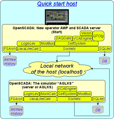
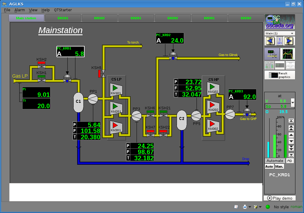
Therefore, our final goal and purpose of this document is to build a complete configuration of the local SCADA station, connected the server, and with the emulation of the data source based on this demo database (Fig.3).
Together, we will get acquainted with such important roles as OpenSCADA as: server of acquisition, archiving, visualization; PLC execution environment and remote development. But before that we will look at OpenSCADA and its capabilities in general.
3.1 General overview
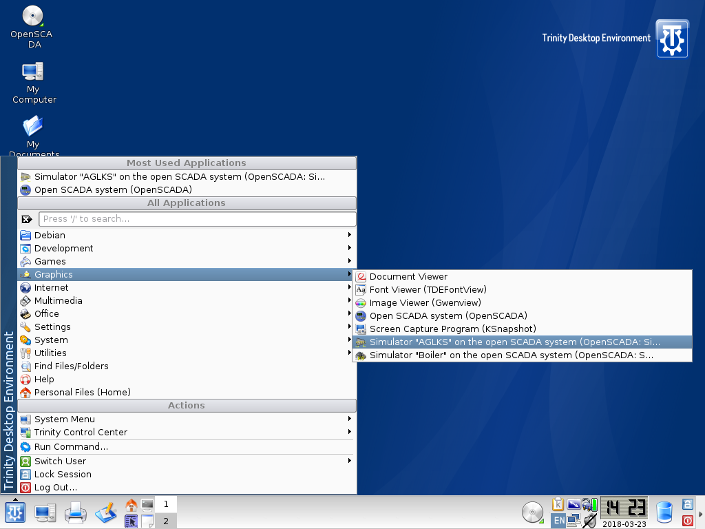
Start up the local execution of OpenSCADA, from the DB simulator "AGLKS", you can from the section "Graphics" of the menu of the desktop environment for the item "Simulator "AGLKS" on the open SCADA system" with a characteristic icon (Fig.3.1.1).
Local start up also can be done from the console by the command:
$ openscada_AGLKS
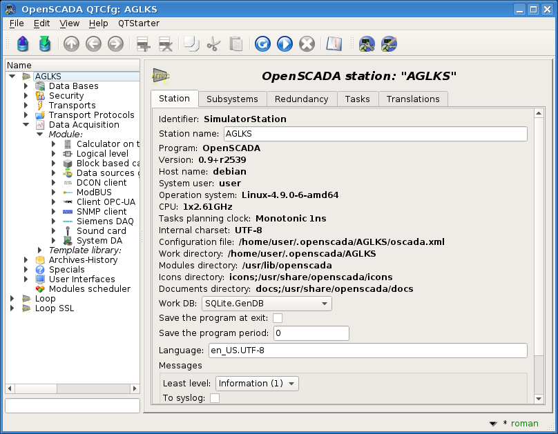
After start up we'll get the window of the OpenSCADA graphical configurator — QTCfg (Fig.3.1.2) with the opened root page. The demo database specially configured so that the first window you'll see after the starting it is the configurator's window. You can then open a window for creating graphical user interfaces, as well as run the user interface project for execution.
The program configurator of OpenSCADA is the main and sufficient instrument for the configuration of any component of OpenSCADA. Like to many other components of OpenSCADA, the configurator is implemented as a module. Besides the QTCfg configurator there available other configurators those perform the same functions, but implemented on the basis of other technologies. For example, these are the Web-configurators: WebCfgD and WebCfg.
All actions in the future, we will overview only in the configurator QTCfg, although all of them can be done in other configurators.
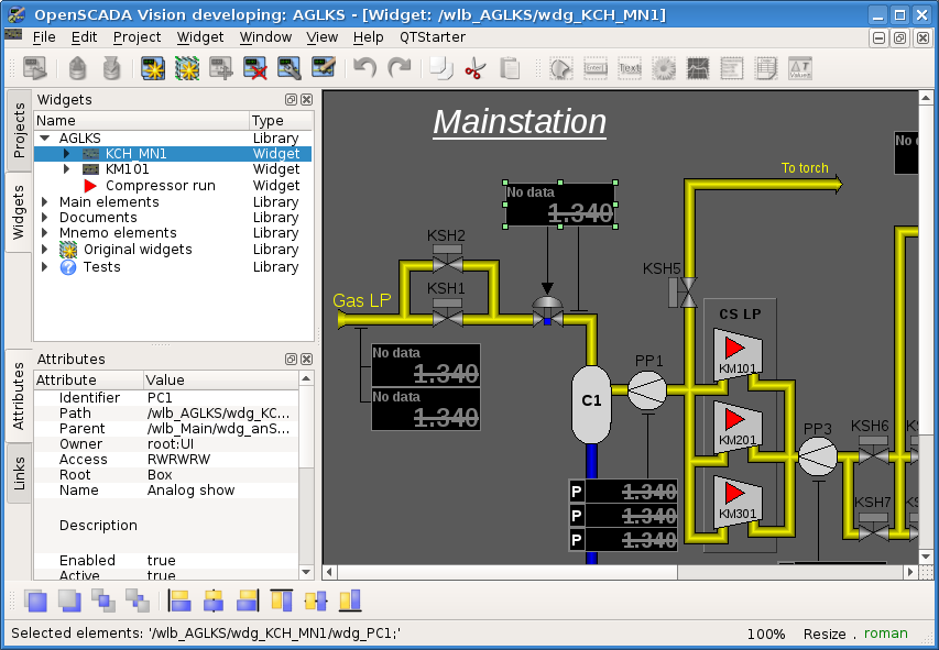
The structure of interface of the configurator window can be considered in detail by the link. It is more important now for us to overview all the available interfaces OpenSCADA, so click next to the last icon in the top on the toolbar. After clicking on this icon the window of development of the user interface will be opened (Fig.3.1.3).
Then we can start up execution of the "AGLKS" project. To do this, select it in the list of the projects and run by clicking on the first left icon on the toolbar or in the the popup menu. The result will be the window of the end interface of the user — the operator (Fig.3.1.4).
Building and executing of the user interfaces is implemented by the Vision module of the "User interfaces" subsystem. In addition to this module the other modules of visualization is accessed. For example, OpenSCADA provides the WebVision module, which allows to execute projects, previously developed in the "Vision" interface module, through the Web-based technologies and by standard Web-browser.
All actions in the future, we will overview only only in the interface of the "Vision" module.
So we ran the demo of OpenSCADA and familiarized with the main set of the tools. In the future, we will use them in the OpenSCADA configuration to perform the functions of the "top level" — AWP operator, and other tasks.
![]() Close the program through the appropriate menu item "File", which must be made obligatory, otherwise its further background launch will not be able to open ports already busied by this program.
Close the program through the appropriate menu item "File", which must be made obligatory, otherwise its further background launch will not be able to open ports already busied by this program.
3.2 Background and remote execution — server, PLC execution environment and remote development
As you will see right now, there are no problems and needs of any additional configuration or addition of the existing configuration, demo one in our case, to run it in the background mode (demon mode) with the provision of server functions.
To run OpenSCADA in the background, we need to install the openscada-server package as described in the installation part and which will already be set in the case of the live disk. After the installing this package, we have to do the following steps, in the console terminal (for example, the program "konsole" in the live disk environment at the Alt+F2 startup dialog) and from the superuser:
# Connect from the superuser
$ su -
# ... for the live disk environment and some other Linux environments
$ sudo bash
# Stop down of execution of the empty server configuration
$ service openscada-server stop
# Create a link of the server project to "AGLKS"
$ rm -R /usr/share/openscada/server
$ ln -s AGLKS /usr/share/openscada/server
$ ln -s /etc/oscada_AGLKS.xml /usr/share/openscada/server/oscada.xml
# Start up the server with the demo DB already
$ service openscada-server start
In this way, you will get the demo database that works in the background, which, however, we will not see until we try to connect to this configuration, as below. Now, every time you start the computer, it will be launched in this way and run in the background. In general, this is the way tor starting up and execution the server configurations, PLC environments and one-board PCs similar to RaspberyPi.
If you still have problems working with the console-terminal, or you deliberately want a background run in the graphical environment — the so-called "start or close in the system tray", then at this stage you can re-run the demo configuration, as described in the beginning of this section (Fig.3.1.1), set the Collapse or startup to the system tray option of the UI.QTStarter module and close the configuration window so that the AGLKS simulator project collapses to the system tray.
3.3 Your own project creation
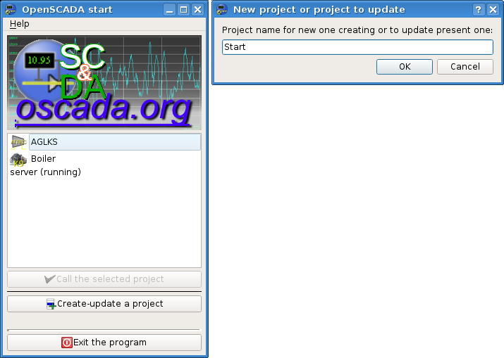
In the window of the OpenSCADA project manager (Fig.3.3), we will create our own project, which can be called from the desktop environment menu in the "Graphics" section, the general item "Open SCADA system" with the characteristic icon (Fig.3.1.1) or the command from the console-terminal:
$ openscada
In this window, we can also check the background execution of server and demo configurations.
That is, press the corresponding Create-update project button and enter the name of the new project, for example Start.
3.3.1 Connecting and using remote and background configurations
Now we can try to connect remotely to the background demo project, look at its configuration and launch the demonstration project on the local execution from the visualization server.
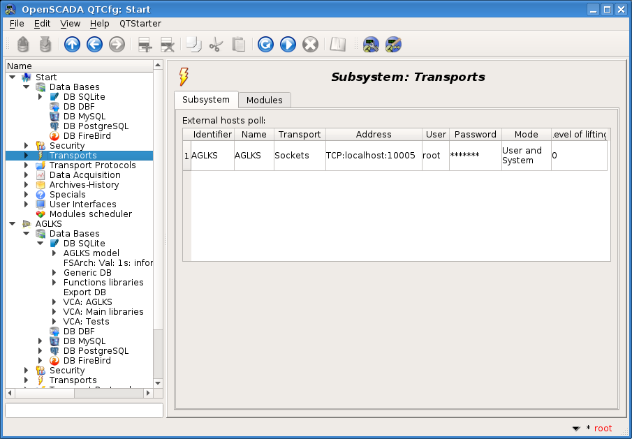
On the transport page (Fig.3.3.1.1), in the User and System mode, we will create a connection to our background demonstration "AGLKS" as an OpenSCADA station. We specify there the transport Sockets, the address TCP:localhost:10005, the user root and the password openscada. After updating the configurator tree, at the command in the context menu, we must get a new root item of this connection and we can control the remote background station from this configuration.
![]() If the remote station item appears but displays a lack of connection, then you have made a mistake in the configuration above or the remote station is not available, which in our case can mean only that it does not work in the background, and then return to the proper section and repeat the operations in it.
If the remote station item appears but displays a lack of connection, then you have made a mistake in the configuration above or the remote station is not available, which in our case can mean only that it does not work in the background, and then return to the proper section and repeat the operations in it.
If everything works then we will save this configuration by clicking the second icon on the left in the toolbar above, because we going to still use it to directly gating the data acquisition parameters from the demon project as PLC.
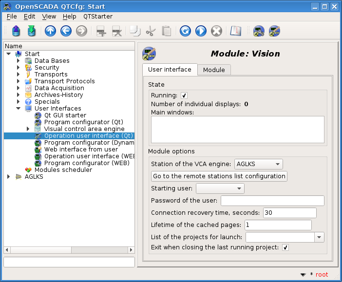
On the configuration page of the UI.Vision visualizer (Fig.3.3.1.2), we will select:
- station of the VCA engine — AGLKS;
- starting user — leave blank;
- user password of this remote station — leave blank;
- project(s) for their automatic execution — also leave blank, because we want to see the possibility of remote development.
The next launch of the UI.Vision module, the second end icon on the toolbar above, should lead the visual development environment to a connection to the visualization project of the background demon project. Where you can perform remote development (fig.3.3.1.3) and run projects from this visualization server for execution (Fig.3.3.1.4).
![]() This configuration of the remote connection to the visualizer server is not necessary to save and the configuration field "Station of the VCA engine" (Fig.3.3.1.2) should be returned to Local and the station user set to root; only then save.
This configuration of the remote connection to the visualizer server is not necessary to save and the configuration field "Station of the VCA engine" (Fig.3.3.1.2) should be returned to Local and the station user set to root; only then save.
The ability to remotely connect and develop is sometimes the only way to develop or correct not only server configurations with the WEB interface only, but also for configurations with the locale visualization, when the locale environment itself is not suitable or limited to execute the development environment of the UI.Vision module, such as smartphones, tablets, and other small screen mobile devices, exclusively with touch input (Android) or restrictions such as the inability to open the system virtual keyboard (Nokia N9). But this remote development can mostly be done in the process of executing a project — the hot development, that is especially relevant for Web interfaces and local interfaces that run only in the execution window. As for remote configuration is one local configurator, as the administration center, can collect all the remote stations in the network, including the stations in the hidden networks of the first level stations, which can be raised by the "Level of lifting" argument (Fig.3.3.1.1).
3.3.2 Connecting the standard OpenSCADA libraries
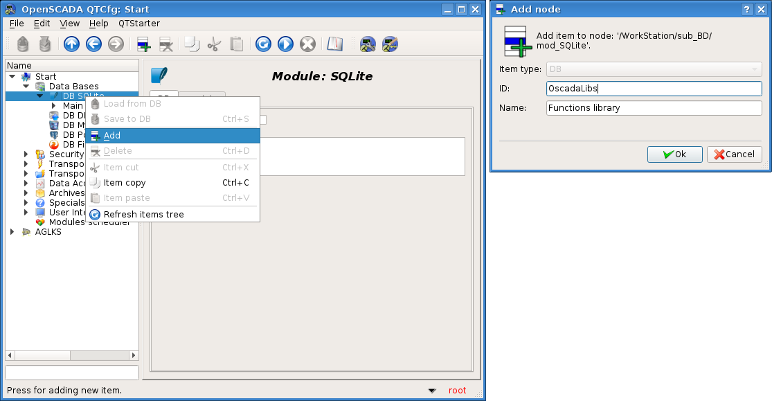
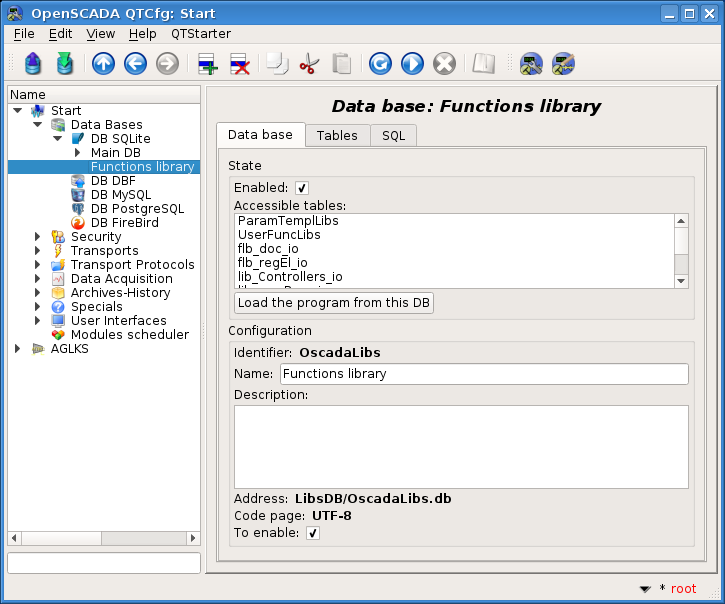
The newly created OpenSCADA project does not contain any specific configuration, in fact it is empty and provides for the user to create a new configuration in the local SQLite database file "St.db", which is located in its own directory of the project with the same name. It is easier to create a complex project of the SCADA system using libraries of functions of the API of the OpenSCADA object model and libraries of the graphical elements, as well as other OpenSCADA libraries. To use the OpenSCADA libraries, you need database files where the libraries are stored: connect-add in the object of the database module "SQLite" (Fig.3.3.2.1), install-select the address and specify the database encoding in UTF-8 (Fig.3.3.2.2).
OpenSCADA distributions are supplied with a number of libraries in the form of database files "SQLite" (table 3.3.2), which, when started-created a custom project, are located in the "LibsDB/" directory. According to this list, we add them all to the object of the database module "SQLite", we set the sign "To enable" and save. Next, to download the contents of the libraries, you can enable the database and click on the button "Load the program from this DB", however, when downloaded, a number of new objects are not enabled (the loading command), so it's easier to complete the new project and run it again, than turning on everything you need manually.
Table 3.3.2. OpenSCADA libraries included in the distribution.
| ID | Name | Address | Languages/charset |
|---|---|---|---|
| OscadaLibs | Functions libraries | LibsDB/OscadaLibs.db | EN,UK,RU/UTF-8 |
| vcaBase | VCA: Main libraries | LibsDB/vcaBase.db | EN,UK,RU/UTF-8 |
| vcaTest | VCA: Tests | LibsDB/vcaTest.db | EN,UK,RU/UTF-8 |
| vcaElectroEls | VCA: Electrical elements library of the user interface | LibsDB/vcaElectroEls.db | EN,UK,RU/UTF-8 |
As a result of adding OpenSCADA libraries you will get an environment ready for adding data sources, defining their history and forming the interface of your own SCADA-system project.
4 Working with data sources
The main function of any SCADA-system is to work with data sources of realtime, that is the polling of the programmable logic controllers (PLC) and simple modules of MOD. For more details see the document "Data acquisition in OpenSCADA".
Support for a given data source depends on the protocol or API, according to which the source provides its data, and the availability for the protocol-API of the module of the subsystem "Data acquisition" in OpenSCADA. The total list of modules of the subsystem "Data acquisition" and documentation on them can be found here in the appropriate table part.
Data from the sources is further processed, archived and used for visual representation of the TP operator.
4.1 Data acquisition from the TP device
As an example let us examine and create the acquisition for the air cooler device. The background demo database, as a PLC and data source, contains the real-time model of the compressor station with six compressors. Data for two devices of air coolers "AT101_1" and "AT101_2" of the compressor station "CM101" are available via the ModBus/TCP protocol on the 10502 port (this port 502 is standard if the access to its opening is available).
We will create the object for the controller to acquire on the protocol ModBUS/TCP and get this data. Thus, we actually realize the task of acquisition real data, since our configuration will be different from working with a real external device only with its address and the address of the ModBUS registers, and it may also be another physical interface of the interaction — the variant of the protocol ModBus. This connection is also a bright example of the ability to implement a data source environment (PLC) based on OpenSCADA.
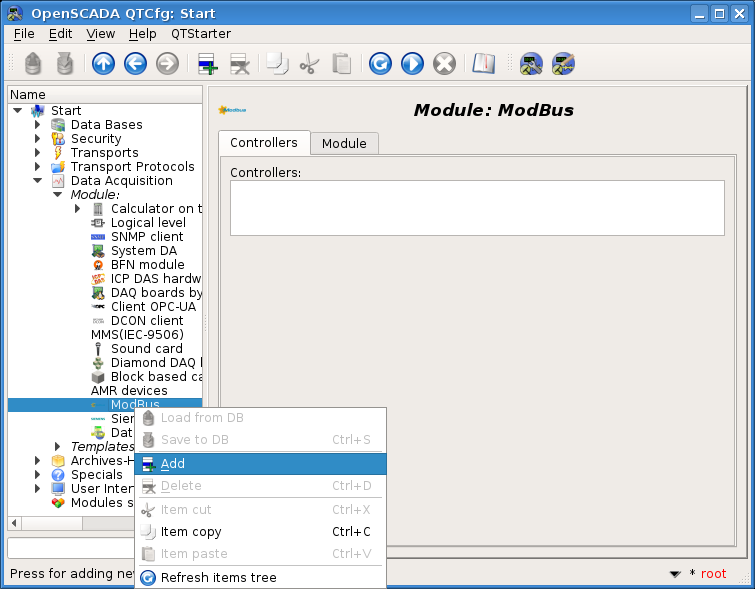
To acquire data by the "ModBUS" protocol in OpenSCADA there the ModBus module of the subsystem "Data Acquisition" is provided. To add a new controller object in the configurator, open the module page "ModBus" ("Start"->"Data acquisition"->"Module"->"ModBus") and in the "ModBus" item's context menu, press "Add" (Fig.4.1.1).
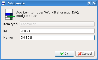
As a result, a dialog box (Fig.4.1.2) will appear asking you to enter the identifier and the name of the new controller object. Identifiers of any objects in OpenSCADA are limited in size to 20 characters and it is recommended that they be entered with the characters of the English alphabet and numbers. In addition, it is desirable to start the identifier from the letter, which will simplify its use in internal procedures. The names of OpenSCADA objects are limited to 50 characters, which can be any. Names are usually used to display, and if it is empty then the identifier will be used. In the future, we can change the name in the object configuration, but the identifier can not be changed directly; however, the object can be cut (Ctrl+X) and then paste (Ctrl+V), renaming it. Enter, according to the remarks earlier, the ID "CM101", the name "CM 101" — CM101 (CM 101).
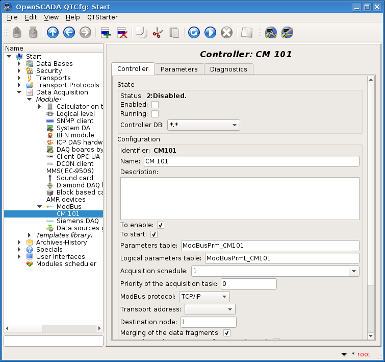
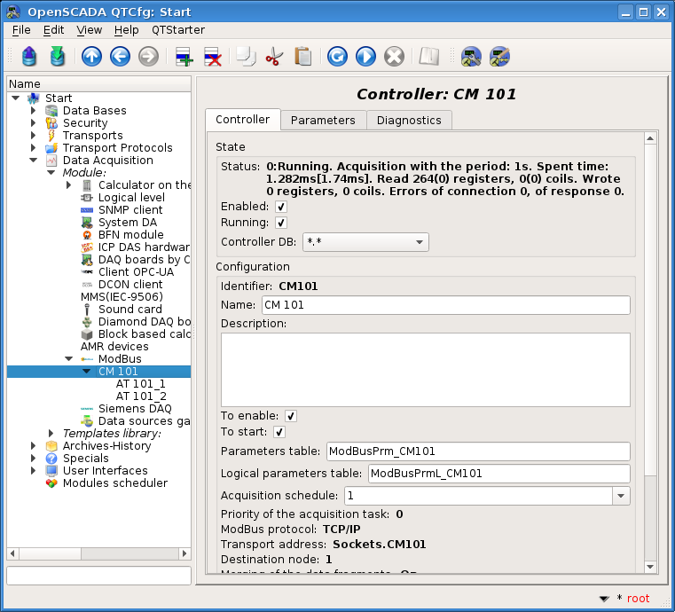
After confirmation, we will have the new controller object. Let us select it in the configurator and acquaint the settings (fig.4.1.3).
Configuring the object to the controller is usually specific to different types of data sources and protocols. For details of settings of the controller object of the module ModBus see to the link. We will consider the general and key settings of this module.
Before configuring communication with your controller, it is necessary, from the documentation for this controller, to find out the settings of its network interfaces and protocols, as well as, in the case of using "ModBus", get a table of assigning external and internal signals of the controller to the numbers of the "ModBus" registers — a map of registers.
Using the controller object page, in the "State" section, you can first estimate the current status of the controller object and the actual state of communication with the physical controller, and also to quickly change them. That is, the "Status" field contains the error code and a text description of the current state of communication with the controller. In our case, the object of the controller is disabled. We can enable and run it by installing signs in front of the appropriate fields. Enabled controller object initiates parameters, started up one also launches a task of acquisition (separate thread to the controller object) and provides the ability to transfer data to the controller, through the attributes of the parameters. The "Controller DB" field indicates the database in which the configuration of the object is stored. We will arrange storage in the main database, that is, leave this field default.
In the "Configuration" section, the configuration of the controller object is directly located. Set the following ones, leaving everything else unchanged:
- "Enable" and "Run" indicate what state to move the controller object when the program is started. Set both fields.
- "Acquisition schedule" contains a scheduler configuration to run the data acquisition task. You can get a description of the configuration format for this field from the tooltip. A single number indicates the periodicity of the execution, in seconds. We will specify one second.
- "ModBus protocol" refers to the variant of the ModBus protocol. Possible variants of the protocol are "TCP/IP", "RTU" and "ASCII". Currently, we are interested in the variant TCP/IP, so leave it as it is. Protocols "RTU" and "ASCII" must be installed in the case of communication with the controller through serial interfaces, often it is "RS-485".
- "Transport address" indicates the outgoing transport of the subsystem "Transports", which is used to connect to the controller. In the case of the variant "TCP/IP", we need a transport in the module Sockets, and in the case of the variants "RTU", "ASCII" and serial interfaces, we need a transport in the module Serial. About creation the outgoing transport in "Sockets" and "Serial" will elaborate below.
- "Destination node" indicates the node of the data source or controller in the ModBus network. In our case it should be 1.
- "Merging of the data fragments" enables merging non-matching registry fragments into one block of the request to a specified number of bytes, instead of generating individual queries. Allows you to reduce total acquisition time. Set this option.
Save our changes in the database by clicking the second left icon on the toolbar.
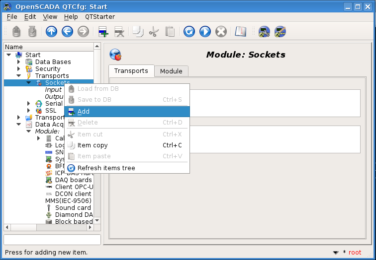
Now, in the same manner as the controller object, let's create the outgoing transport in the module "Sockets" ("Start"->"Transports"->"Sockets") through the context menu (Fig.4.1.4), and call the transport as well as the controller object CM101 (CM 101). Please note that in the "Item type" field, the dialog of enter ID and the name (Fig.4.1.2), you must select Output transport!
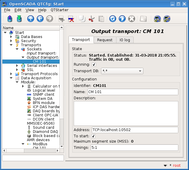
Configuration page of the output transport is shown in Figure 4.1.5. This page also contains the section of the status and operational control. In the "Status" field the textual description of the current state of the transport is contained. We can run it for execution by checking the box in front of the appropriate field. Running object of the transport initiates the connection to the external node. The field "Transport DB" indicates the database to store the configuration of the object. We will use the main storage.
The "Configuration" section directly contains the configuration of the transport object. Set the following ones, leaving everything else unchanged:
- "Address" specifies: the type, address and mode of connection with the remote station. You can view the record format in the tooltip. Set this field to the value TCP:localhost:10502.
Other types of the transports are created similar to the method considered for "Sockets", and their configuration usually differs only in the format of address and timeouts. For converters USB->Serial,Modem that address you may learn into the operation system, for example by the console command $ dmesg, just after it connection.
Let's save the transport object and return to the configuration field "Transport address" of the controller object and select the address "Sockets.CM101". Configuring the controller object is finished, enable it by set the flag "Enabled". The next step is configuration and choose the data you need to query from the controller. This setting is done by creating an parameter of the controller. The parameter allows you to describe the list of data obtained from the controller and to transmit them to the environment of OpenSCADA — the data model.
To add a new parameter we will open the page of our controller object and on the popup menu of the item "CM 101 (CM101)" we'll click "Add". The parameter we'll call AT101_1 (AT 101_1).
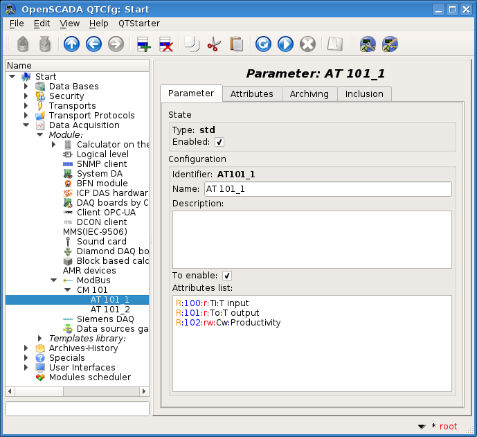
The configuration page of the obtained parameter is shown in Figure 4.1.6. This page contains the section of status and operational control. In the "Type" field it is contained the identifier of the type of the parameter, in this case it is the type Standard (std). We enable this parameter by setting a sign opposite the corresponding field. The enabled parameter is involved in the process of exchanging with the controller.
The "Configuration" section directly contains the configuration of the parameter. Set the following ones, leaving everything else unchanged:
- "To enable" indicates the need to transfer the object to the "Enabled" mode, when the program is started. Set this field.
- "Attributes list" contains the configuration of the parameter attributes relative to registers and bits of "ModBus". You can view the record format in the tooltip. Set the contents of this text field to:
R:100:r:Ti:T input
R:101:r:To:T output
R:102:rw:Cw:Productivity
In the same way, we will create, or copy from AT101_1, a second parameter "AT101_2 (AT 101_2)". The list of attributes for him will be established in:
R:103:r:Ti:T input
R:104:r:To:T output
R:105:rw:Cw:Productivity
Save both the parameters. Now we can start up our controller object for acquisition, for which we will return to its page and in the section "Status" we will set the sign "Running". If we do not miss anything then the exchange will start successfully and in the "Status" field we will get a similar presentation as shown in Figure 4.1.7.
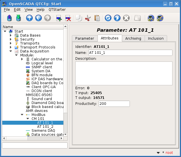
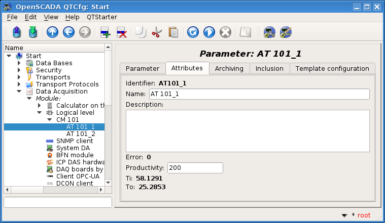
In the case of the successful exchanging with the physical controller, we'll also obtain the described data of the controller in the infrastructure (the data model) of OpenSCADA. You can see these data in the tab "Attributes" of our parameters AT101_1 (Fig.4.1.8) and AT101_2. Since the acquisition is done regularly and periodically per second, we can observe their change by clicking on the "Refresh current page" button in the toolbar.
On this, configuration of the data acquisition is considered complete.
4.2 Processing received data of the TP
Often there is a situation where the input data from the data source is "raw", that is, unprepared or inconvenient for the visual representation, therefore, it is necessary to carry out this preparing. In our example, we get the data that comes in the code from the scale inside the controller and our task is to make a calculation of real values from the obtained data. Data processing in OpenSCADA can be done either directly in the visualization, or in the subsystem "Data acquisition". However, mixing the process of the visualization and processing of the input data: confuses the configurations, prevents the history of real data, makes the resulting visualization shapes less suitable for reuse and increases the load on the visualization thread, thereby reducing its overall sensitivity. Accordingly, we will prepare the data in the subsystem "Data acquisition".
Calculations in the subsystem "Data acquisition", for the real data obtaining, are mostly done via the module of the logic level LogicLev and the templates of parameters of the subsystem "Data acquisition". The module ModBus is a rare case where such calculation can be made directly in it, as we will see below. To familiarize with the concept of "Logical level" you can here.
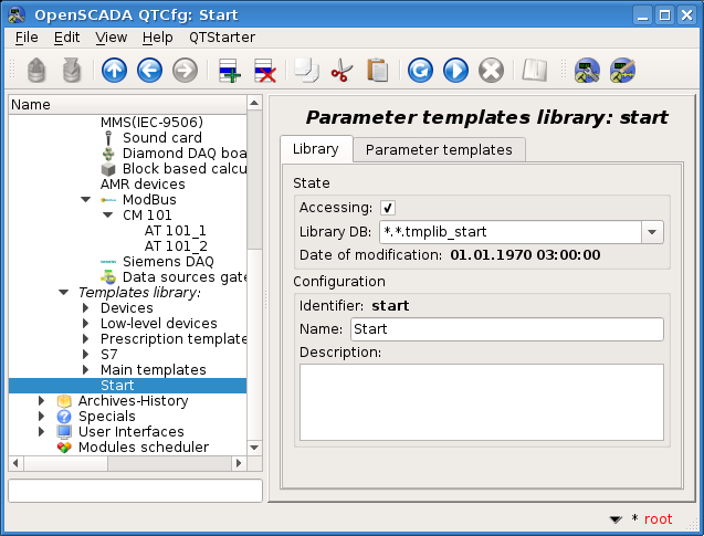
To perform calculations in the logical level module, you must first create a library of templates of our project and a parameter template of the subsystem "Data acquisition" in it. To create a template library, go to the page of the subsystem "Data acquisition" and, through the context menu, create a template library "start (Start)". The configuration page of the obtained object of the templates library (Fig.4.2.1) contains the status and operations section "State" and the section "Configuration" that contains only the default configuration fields and which will remain unchanged. In general, we have:
- The section "State":
- make the library accessible by setting a sign opposite the corresponding field;
- specify the storage in the field "Library DB", leave it by default — the main DB of the project;
- can control the date of the last modification.
- Save the object.
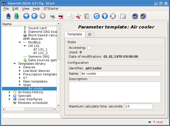
To create a template, open the page of the newly created template library ("Start"->"Data Acquisition"->"Templates library"->"Start") and, through the context menu, create an object of the template airCooler (Air cooler). The configuration page of the obtained object of the template (Fig.4.2.2) contains the status and operations section "State" and the section "Configuration" that contains only the default configuration fields and which will remain unchanged. In general, we have:
- The section "State":
- make the template accessible by setting a sign opposite the corresponding field — the available templates can be connected to the data acquisition parameters, and the parameters will be calculated based on this template;
- we can control the number of objects that use this template to calculate the context of the parameter;
- can control the date of the last modification.
- Save the object.
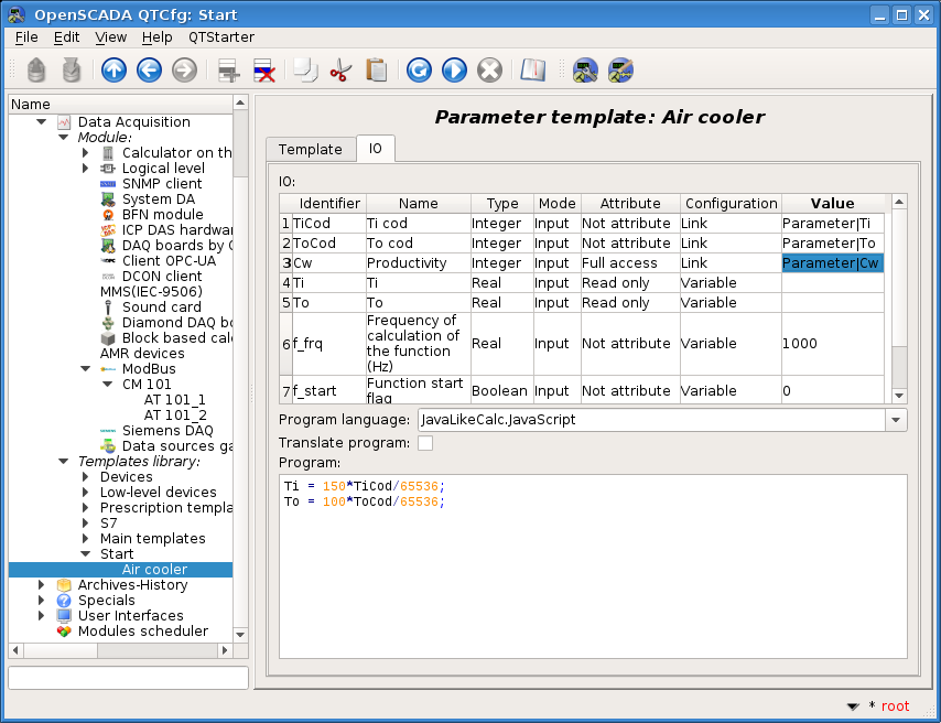
The basic configuration and the formation of the template of parameter of data acquisition is made in the tab "IO" (Fig.4.2.3) of the template. The detailed description of the process of the template formation can be found at link.
In the template we will create two properties for inputs ("TiCod", "ToCod"), two for output ("Ti", "To") and one transparent ("Cw"). For properties "TiCod", "ToCod" and "Cw" we will set the sign "Configuration" in Link, which will allow them to tied up a "raw" source. For parameters "Ti" and "To", the sign "Attribute" will be set to Read only, "Cw" to Full access; to form three attributes of the result data acquisition parameter: two read only and one for full access.
Set the language of the program in JavaLikeCalc.JavaScript, and the program in:
Ti = 150*TiCod/65536;
To = 100*ToCod/65536;
Save the obtained template and establish a sign of availability (Fig.4.2.2).
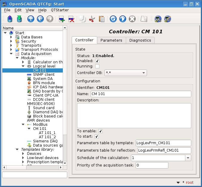
Now we will create the controller object and parameters in the "LogicLev" module of the subsystem "Data acquisition". The "LogicLev" controller object and its parameters are created identically to the "ModBus" module earlier on the page: "Start"->"Data acquisition"->"Module"->"Logical Level". We name them identical to the objects of the module "ModBus".
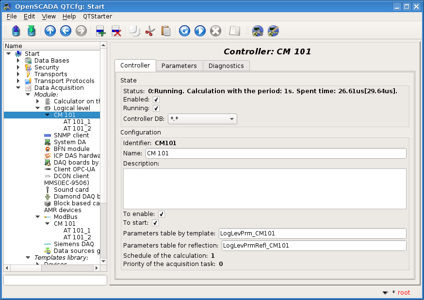
The controller object of the module "LogicLev" (Fig.4.2.4) has no specific settings and the default ones may not be touched except the "Schedule of the calculation" field, which will install in one second. Before adding parameters, you must turn on the controller object by checking the "Enabled" flag.
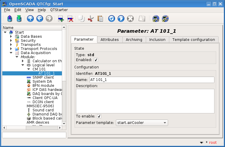
Parameter of the controller object of the "LogicLev" module (Fig.4.2.5) has the specific setting "Type", where you need to set Logical (std) and into the field "Parameter template" select the address of the template, we have just created.
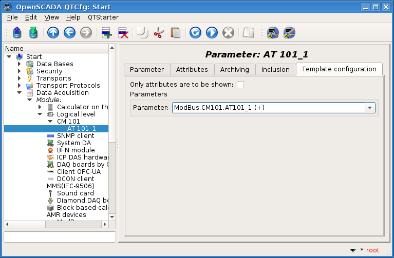
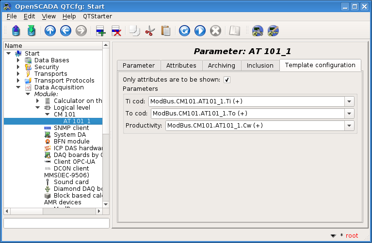
In addition to the basic configuration of the parameter it is necessary to configure the attached template (Fig.4.2.6). Configuration tab of the template appears in the parameter's mode "Enabled". To enable the parameter it is possible by the previously enabling the controller object. The flag "Only attributes are to be shown" allows you to set apart each link (Fig.4.2.7). Since we, in the template, forcibly described the format of the links as "Parameter|Ti", we can establish all three links by simply pointing the address to the parameter in the controller object "ModBus". Specify-select the address ModBus.CM101.AT101_1 and ModBus.CM101.AT101_2 in the appropriate parameters.
It should be noted that all the fields for entering object addresses in OpenSCADA have a mechanism for selecting the address. This mechanism involves elemental choice, during which there is a movement in the interior. For example, selecting the address "ModBus.CM101.AT101_1" first we will be able to choose the type of data source, including the item "ModBus". By selecting the item "ModBus" in the list of available items for selection the controller objects of the module "ModBus" will be added, among which will be "ModBus.CM101". Select the item "ModBus.CM101" add the controller parameters to the list, etc. to the final element in accordance with the hierarchy of objects. For the possibility of returning to the level above, the elements of all the higher levels from the current address value are inserted into the list of choice.
Let's save the created objects of the controller and parameters, after which we will start up the controller object by setting the "Running" sign in the "State" section. If we do not miss something, the calculation is successfully started and in the "Status" we'll get something like to Figure 4.2.8.
In the case of successful processing of the template code, in the parameters, we'll obtain the processed data in the infrastructure (the data model) of OpenSCADA. You can see these data on the tab "Attributes" of our parameters AT101_1 (Fig.4.2.9) and AT101_2.
On this, the configuration of the data processing is considered complete.
4.3 Complex object-tag of the signal
The previous sections described the mechanism of connecting the data source as an apparatus object — "Air cooler", which involves combining all the signals in one object of the data source parameter. However, the more common approach to large automation is the formation of a parameter object around an individual signal, for example — "Temperature at the output of the refrigerator AT101_1 (TE1314_1)", which are often called tags.
Creating the parameter object around the signal allows to formalize its description to the templates of analog and digital signals by including to them all necessary processing, alarming and other characteristic information. For a simple configuration of the typified analog and digital signals there are the parameter templates in the OpenSCADA libraries, and many of the visual presentation shapes are adapted to work and binding with these parameters directly, without going into details on the attributes.
Typically, for creating a parameter based on a template, the LogicLev module is used as described in the previous section. However, a number of modules, including ModBus provide the ability to immediately create logical parameters, based on the template. We will add new parameters by opening the page of our earlier created ModBus controller object and clicking "Add" button on the "CM 101 (CM101)" menu item in the configurator.
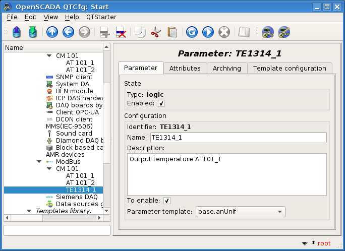
We name the analog parameter TE1314_1 (TE1314_1) (Fig.4.3.1). The parameter type is set to Logic, the parameter template is selected by base.anUnif, the description will be set to Output temperature AT101_1, set the flags "To enable" and "Enabled". Next, we need to configure:
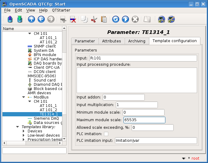
- The parameter template in the tab "Template configuration" (Fig.4.3.2):
- the "Input" field is set to ModBus-register's address of this parameter R:101;
- the "Maximum module scale" is set to 65535, which corresponds to 100 °C.
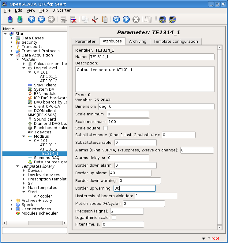
- The tab "Attributes" (Fig.4.3.3) settings:
- "Dimension" to deg. C;
- "Scale:minimum" to 0;
- "Scale:maximum" to 100;
- "Border up alarm" to 40;
- "Border up warning" to 30.
- Save the object.
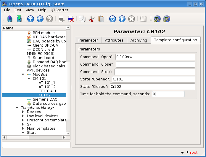
The discrete parameter is called CB102 (CB102). The parameter type is set to Logic, the parameter template is selected by base.digitBlockUnif, set the flags "To enable" and "Enabled". Next, we need to configure:
- The parameter template in the tab "Template configuration" (Fig.4.3.4):
- the "Command 'Open'" field is set to the value of the ModBus-bit address of the parameter C:100:rw;
- the "State 'Opened'" field is set to the value of the ModBus-bit address C:101;
- the "State 'Closed'" field is set to the value of the ModBus-bit address C:102;
- the "Time for hold the command" field is set to 0, because the command if not the pulse one.
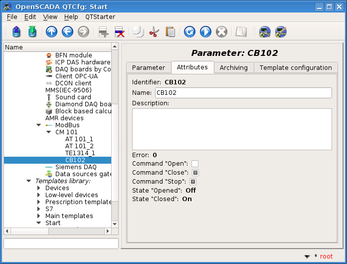
- The tab "Attributes" (Fig.4.3.5) settings: make sure the availability of the command and states.
- Save the object.
4.4 Getting for ready data of OpenSCADA — gateway
Having familiarized with the typical mechanisms for obtaining the data, described in the previous sections, you must imagine already the total amount of work on their getting and processing, that is, formalizing and obtaining this data in the SCADA-system data model. If you add here the task of creating these data at the PLC level — the PLC data model of freely programmable PLC, and transforming it into the data model of the exchanging protocol, then you should notice a triple data transformation here. About the transformation into the protocol data model — serialization, this is determined by the physical properties of the communication channels and is carried out automatically, but the formation of the PLC data model and SCADA-system data model is carried out by the programmer of the PLC and the SCADA-system, respectively. Moreover, this work has much in common, especially if performed by one person or organization, and therefore there should be mechanisms for its unification.
In the case of a different origin of the PLC and SCADA, greater unification than the protocol layer of the exchange is difficult to achieve. On the other hand, the deep unification of PLC and SCADA data models can be found at the same time by PLC and SCADA manufacturers, which, however, only strengthens their monopoly status and in fact reduces the benefits of unification through the overall cost of the solution.
OpenSCADA provides for the possibility of such unification through the affiliation with the PLC. Such an affinity can only be provided for PLCs that are completely open, they have open-source software installed, and so you can install OpenSCADA as a PLC execution environment. As an execution environment, OpenSCADA can provide PLC data and by the standard protocols such as ModBus, and to obtain these data directly and without any action on them, on the side of the SCADA system there is the module "DAQGate" provided, which, in fact, brings these models together. That is, in fact, the PLC-programmer, which is a SCADA-programmer also, forms a PLC data model, and at the SCADA-level it is already used as a ready-made, which completely removes the stage and works on obtaining, processing and forming the data model of the SCADA-system. Moreover:
- the discrepancy between PLC and SCADA data models is eliminated when they are changed;
- the configuration data, logically and exclusively, is stored on the PLC to which they relate;
- violations and other messages are generated on the primary source — PLC;
- provides for a mechanism for storing archive-history on the PLC both fully and as part of the compensation for loss of communication with the SCADA, especially for bad and wireless communications.
In order to demonstrate and familiarize, we will create here a controller object of the module "DAQGate", to locate the data of our virtual PLC. It is created identically to the controller objects created earlier in the "ModBus" and "LogicLev" modules, on the page: "Start"->"Data acquisition"->"Module"->"Data sources gate" and name it AGLKS.
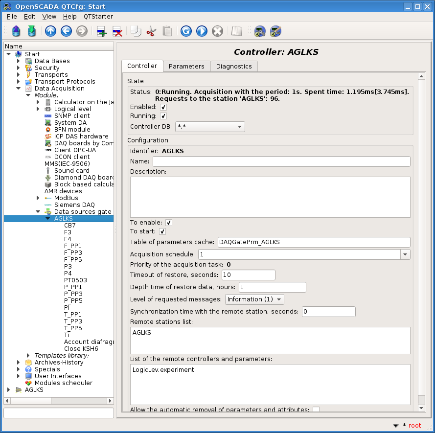
Controller object of the module "DAQGate" (Fig.4.4.1) has the following specific settings that we must accomplish:
- "Remote stations list" — in the "Append station" field, we will select the previously established connection of the remote station "AGLKS".
- Enable the controller object.
- "List of the remote controllers and parameters" — in the "Parameters tree" field select LogicLev.experiment and then <<Append current>> above this list.
- Start up the controller object.
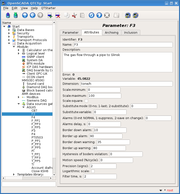
If everything is done correctly, then the parameters of the selected controller will automatically be created and we can look at the data on them in the tab "Attributes" (Fig.4.4.2).
4.5 Archiving-history of the TP data
The data obtained above are considered current, that is, those that are periodically updated and characterize the value of the parameter TP for the current time. At the same time, the previously read values are lost when they are overwritten by the current value, that is, their history is missing. In many tasks, the archive-history of the read values of TP parameters is required, for which OpenSCADA provides the subsystem "Archives-History" where we need to create value archivers and messages, for violations, and specify our parameters for archiving their values there.
![]() If you do not create archivers and do not connect our parameters to archiving by them then on charts you will not get the history more than its total width, and also lose the accumulated during switching, and in the reporting documents you will not get the history at all.
If you do not create archivers and do not connect our parameters to archiving by them then on charts you will not get the history more than its total width, and also lose the accumulated during switching, and in the reporting documents you will not get the history at all.
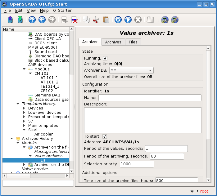
Let's start with the archiving of values, for which it is necessary to create at least one archiver for the required type of storage and the values periodicity. In general, OpenSCADA includes two archiving modules: to the file system "FSArch" and to the database "DBArch". Here we will consider only the module of archiving on file system, as the most universal and effective one. Concerning the periodicity of values, for the "high-quality" archiver, it is preferable to choose the periodicity of the values of the slowest source of data in our system, which we have one and we specified the periodicity for him in 1 second. To create a value archiver, open the archiving module page ("Start"->"Archives-History"->"Module"->"Archiver on the file system") and, through the context menu, we will create an object of the value archiver 1s. Note the value of the "Item type" field in the creation dialog, which should be the Value archiver! The configuration page of the resulting object of the value archiver (Figure 4.5.1) contains the status and operational control section "State", the configuration section "Configuration", and the section of the specific settings for the archiver module "Additional options". In general, we have:
- Section "State":
- start up the archiver for execution by setting the sign opposite the corresponding field — only running archiver performs the archiving;
 to establish last and after the execution of all this list;
 - we can control the current and maximum time of the archiving session;
- specify the configuration storage in the field "Archiver DB", leave the main DB of the project, by default;
- we can control the total archive files size of this archiver.
- start up the archiver for execution by setting the sign opposite the corresponding field — only running archiver performs the archiving;
- Section "Configuration":
- set the startup the archiver when the program is started, by setting the sign opposite the corresponding field;
- set the address of the archive folder in ARCHIVES/VAL/1s, which is by default;
- set the period of values to 1 second;
- Set the archiving period to 60 seconds, by default; usually it is the same for archivers with any periodicity of values.
- Save the object.
One the "high-quality" archiver is already sufficient for most tasks, but if you plan to build graphs-trends of the values and reporting documents at a great depth (days, weeks, months) then you need to create a couple of archivers with more periodicity of the values. Otherwise, the construction of the graphics and documents will be long and/or be cut off by the time limits! Typically, such additional archivers are created, but you must create them identically for the "high-quality" archiver above:
- Minute: the identifier 1m, the address ARCHIVES/VAL/1m and the value period 60 seconds.
- Hourly: the identifier 1h, the address ARCHIVES/VAL/1h and the value period 3600 seconds.
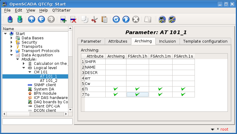
To activate the archiving of the attributes "Ti" and "To" of the AT101_1 and AT101_2 parameters in the previously created controller of the "LogicLev" module it is enough on the "Archiving" tab of the configuration page to choose which attributes are to be archived and by what archivers (Fig.4.5.2). We'll choose the archiving of "Ti" and "To" attributes by the previously created archivers FSArch.1s, FSArch.1m, FSArch.1h. The same thing you can do for the attribute "var" of the analog parameter "ModBus.CM101.TE1314_1" and for "com" of the digital parameter "ModBus.CM101.CB102".
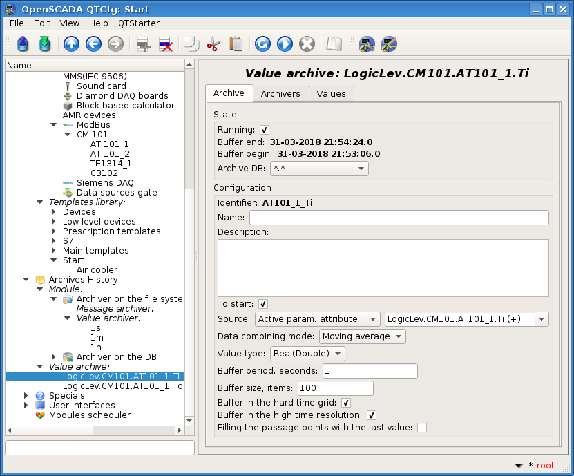
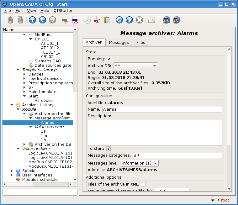
As a result of this operation, archival objects for the selected attributes will be created automatically. An example of the archive object, for the attribute "Ti" of the parameter AT101_1, is shown in Figure 4.5.3.
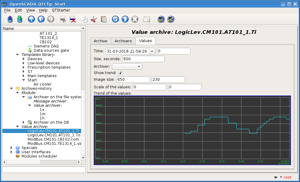
Usually the settings of the archive do not need to be changed, but if you need special configuration, it can be done on the aforesaid page. Often you may need to obtain the information about the archive. For example, find out the size of the archive both in time and on the storage, as well as look at the graph of the parameter (Fig.4.5.4).
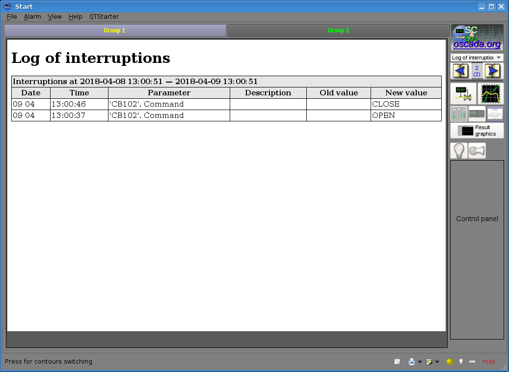
Controller objects, as well as individual parameter templates, can generate alert messages, for example, complex signal-tag templates generating messages when output values over one of the borders. Messages of this nature have a specific category and are called violations.
OpenSCADA messages previously come to the messages buffer, which acts as the primary archive. However, the buffer has a limit and is stored only in RAM, that is, it is lost when the program is restarted. The role of storing messages in one or another storage is performed by the message archivers, as the value archivers for the values.
Accordingly, we will create a message archive for archiving of violations, for which we will open the archiving module page ("Start"->"Archives-History"->"Module"->"Archiver on the file system") and, through the context menu, we will create an object of the message archiver alarms (Alarms). Note the value of the "Item type" field in the creation dialog, which should be the Message archiver! The configuration page of the resulting object of the message archiver (Figure 4.5.5) contains the status and operational control section "State", the configuration section "Configuration", and the section of the specific settings for the archiver module "Additional options". In general, we have:
- Section "State":
- start up the archiver for execution by setting the sign opposite the corresponding field — only running archiver performs the archiving;
 to establish last and after the execution of all this list;
 - specify the configuration storage in the field "Archiver DB", leave the main DB of the project, by default;
- we can control the time of the first and last message in the archive of this archiver;
- we can control the total archive files size of this archiver;
- we can control the current and maximum time of the archiving session.
- start up the archiver for execution by setting the sign opposite the corresponding field — only running archiver performs the archiving;
- Section "Configuration":
- set the startup the archiver when the program is started, by setting the sign opposite the corresponding field;
- set the category of messages that characterizes the violations to al*;
- set the level of archived violations in Information (1);
- set the address of the archive folder in ARCHIVES/MESS/alarms, which is by default;
- Save the object.
In the same way, you can create message archivers of a different nature, for example, the actions of the operator, for which it is enough to define the category of these messages and to form for them a template or regular expression rule. You can study main page of the subsystem "Archives-History" for information on their categories and set up a template or regular expression rule. You can even create an archiver to archive all program messages, and doing so is not recommended because of large archives size and long access to them later.
5 Formation of the visual representation
The formation of the visual representation may be performed at three levels of complexity and the user can select any of them, depending on demands of the task, level of his knowledge and availability of libraries with ready-made shapes and templates.
The first level requires a minimum qualification of the user, but implies the presence of libraries of the template frames, which are needed to solve his task. Within the limits of the first level the user only has to know how to connect the dynamics to pages of the template frames and how to add new pages of the template frames.
The second level provides the additional ability, that is to create new frames based on the finished-complex elements, simply by their placement in the frame area. To achieve this qualification level, the user will need libraries of complex elements needed to solve his tasks.
The third level requires that the user is able to use of all the tools of the development environment of the visual interfaces of OpenSCADA, including the creation of new complex elements and developing of the user interfaces in the project.
All the works on the visualization interface we will make in the environment of the module "Vision" of the subsystem "User interfaces". To open the "Vision" interface window you should click the second icon on the right on the configurator toolbar. The result is the window previously shown in Figure 3.3.1.3.
The interfaces of user-operator realizing into OpenSCADA by the projects of visualization. Into the main elements library of the user interface the typical project template has presented, which based on the concept of the signal objects and views of displaying. The user can start for creation self concept of the visualization interface, by a new project, or can use the specified template.
![]() To implement a new concept of the visualization project, you will need the knowledge of the third level and significant efforts outside of the consideration of this document. Therefore, we will consider creating a visualization interface based on the accessible template project.
To implement a new concept of the visualization project, you will need the knowledge of the third level and significant efforts outside of the consideration of this document. Therefore, we will consider creating a visualization interface based on the accessible template project.
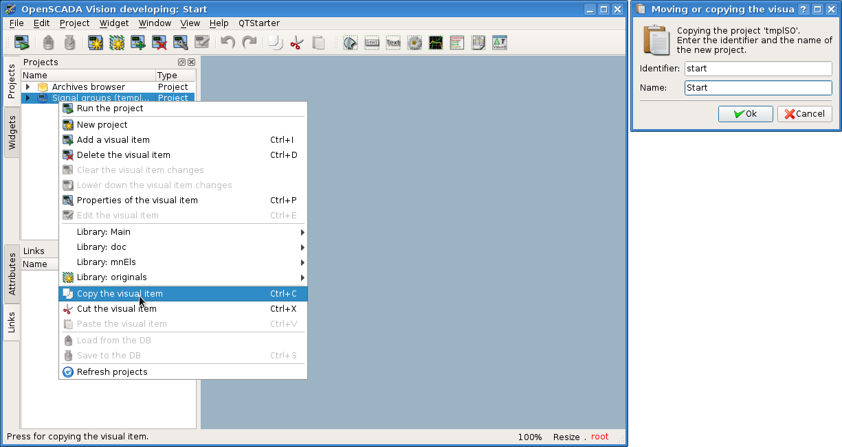
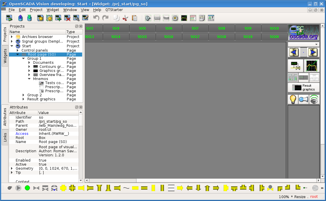
Copy the project "Signal groups (template)", by first clicking the button "Copy the visual item" on it, and then the button Paste the visual item (Fig.5.1). In the dialogue we will call our new project start (Start) and in the list of projects we will get the item of our new project (Fig.5.1).
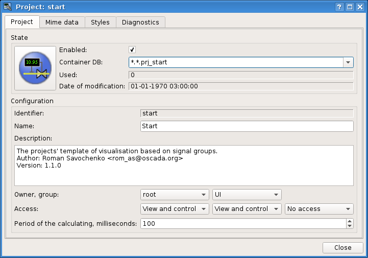
Before using and saving the new project (Fig.5.3), you need to change the address of its storage to the main DB *.*.prj_start that we can do on the main page of the properties dialog of the visual element that is called by the the button "Properties of the visual item" (Fig.5.2). After that, we will save our new project by clicking the third button on the left of the toolbar.
The template project (Fig.5.3) contains two branches: "Control panels" and "Root page". The branch "Control panels" contains typical control panels and set of the special frames. The branch "Root page", with the root page basis, contain subbranches for the signal objects "Group 1", "Group 2" and different branch "Result graphics". The signal object's subbranches "Group {n}" have a number identifier and can expanded by appending up to 20 items. The presence of the grub "Group {n}" is reflected by activating the corresponding button of the signal object of the root page, allowing them to switch. Every subbranch "Group {n}" has containers or templates for display views, typically: "Mnemo", "Graphics groups", "Contours groups", "Groups of overview frames" and "Documents". The presence of pages in containers of the display views enables the selection possibility for the corresponding signal object of the root page. More information about the structure of the root page can be found at link.
5.1 Adding the template page and connecting the dynamics
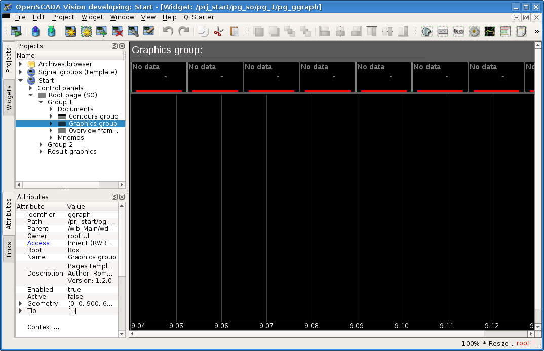
Let's examine the first level of complexity task, when in the already designed interface conception it is necessary to link the dynamics to the template page. The "Template page" idea means a page on the basis and with the help of inheritance there can be created a lot of final visualization pages with an individual list of the dynamics. The examples of these pages are: "Graphics group", "Contours group", "Overview frames panel" and "Result graphics". In Figure 5.1.1 the template page "Graphics group" is presented in the tree of our project "Start".
The template page "Graphics group" provides an opportunity to link up to eight signals for simultaneous display them on the diagram. Elements at the top will automatically hide for unspecified links.
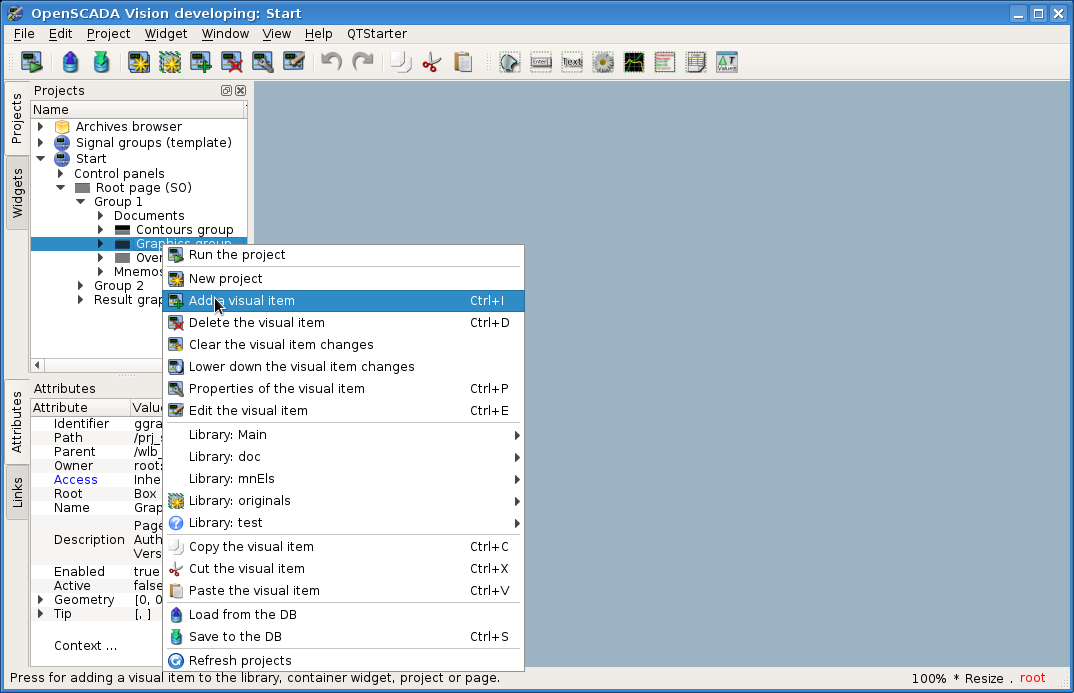
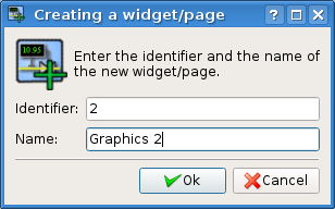
Let's create a new group of graphics in the template container "Graphics group" of the first group of the root page. To do this, let's in the context menu of the item "Graphics group" select the menu item "Add visual item" (Fig.5.1.2). To enter the ID and name of the new visual item the dialog will appear (Fig.5.1.3). Enter the ID "2" and the name "Graphics 2" — 2 (Graphics 2).
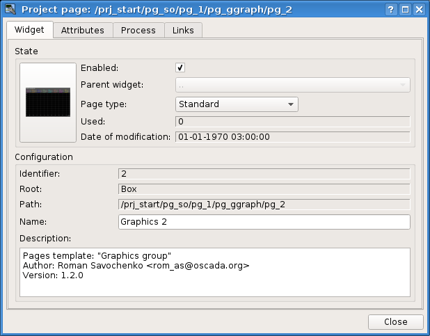
After confirming the name entry, a new page will be created. However, for its activation, we need to enable it. You can enable this page in the dialog of the properties editing of the page (Fig.5.1.4). To open this page it is possible by selecting the menu item "Properties of the visual item" in the context menu of the newly created page. You can create a page in the logical container based on the template by copying the template to yourself, as well as copying another page of this container, but also with links.
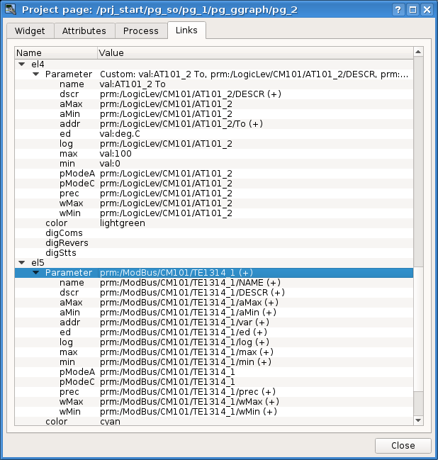
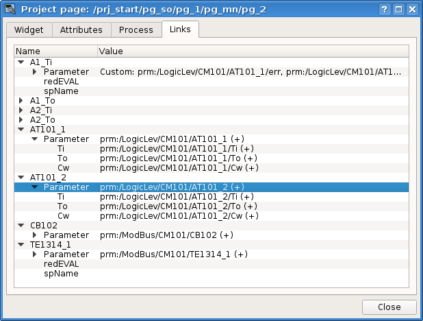
After enabling the page you are ready to set links to the early created parameters of the controllers. To do this, without leaving the dialog of the properties edition of the newly created page (Fig.5.1.4), click on the tab "Links" (Fig.5.1.5). On this tab, we can see a tree with the elements "el1" ... "el8". Expand any of the elements we'll see the branch "Parameter", and exactly in it we have to specify or choose the address of our attributes "Ti" and "To". In general, we fill out four elements, and during this part of the properties you must specify as constants:
- "name" — val:AT101_1 Ti.
- "ed" — val:deg.C.
- "max" — val:150 (for Ti) and val:100 (for To).
- "min" — val:0.
If the template of the controller parameter predicts in advance the attributes presence, specified by us as constant, then only the parameter can be specified, and the attributes are arranged automatically. This can be seen by attaching the previously created complex object-tag of the analog signal "ModBus.CM101.TE1314_1".
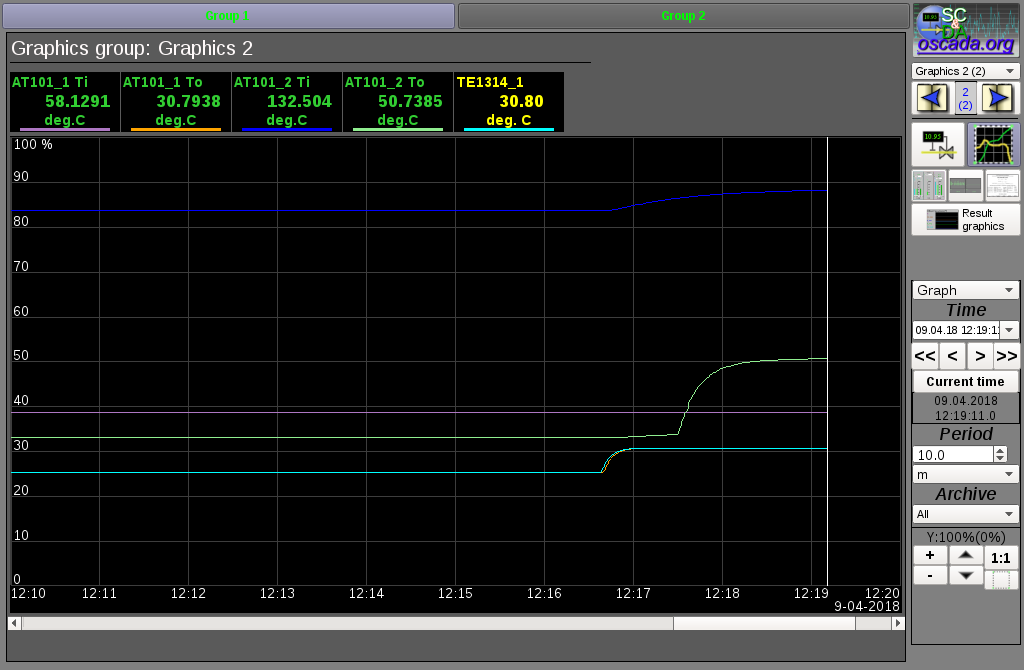
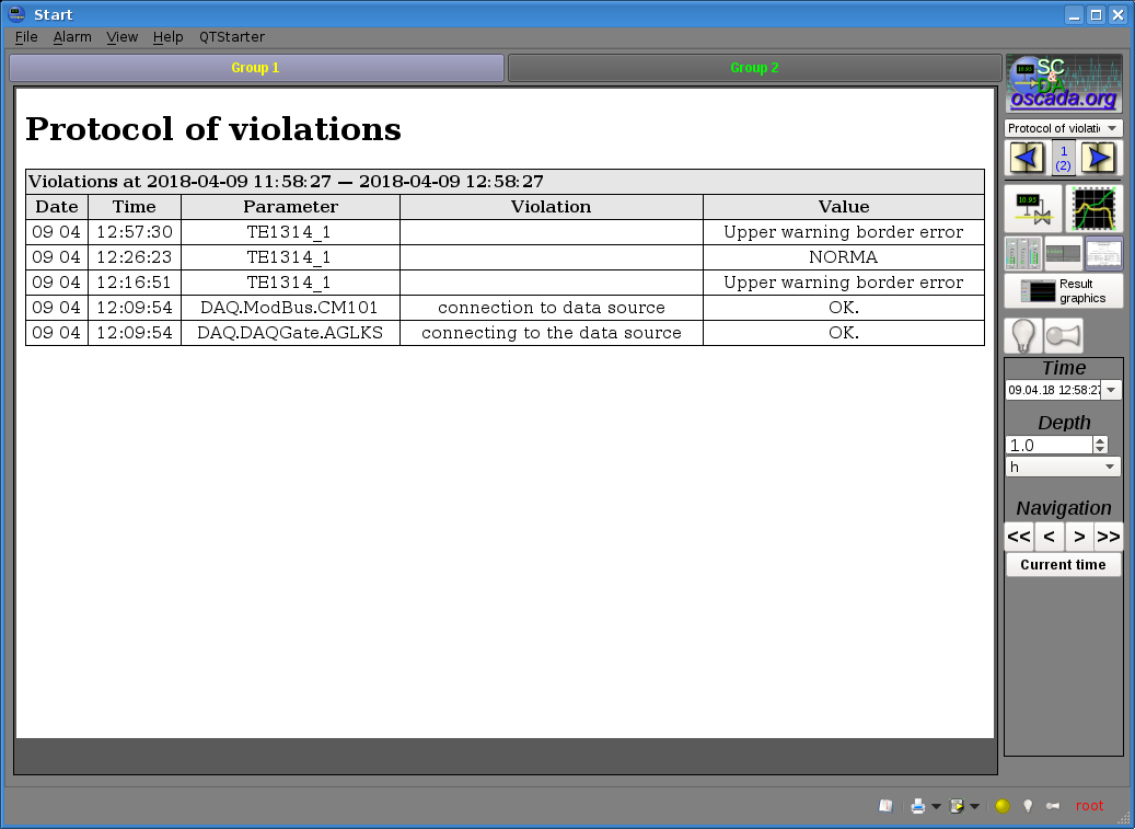
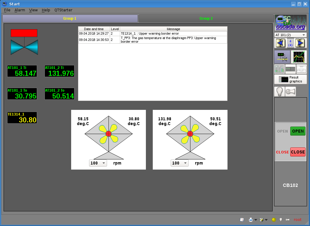
After completing the linking, we can check what happened as a result of our efforts. To do this we'll close the editing properties dialog and run the project "Start" for execution, about the run button we remember from the previous chapters. Then let's choose the graphics and switch to the second page. With error-free configuration, we should see something similar to that shown in Figure 5.1.6. Note that for the parameter of the complex object-tag, with the established limits of violations, the output value beyond the boundary is marked by an emergency color. In order to see the violation abroad you can set the value of the fan's performance in 100 (Fig.4.2.9).
5.2 Creating a new frame — mnemonic schemes
Let's raise the bar and create a new frame, on which we'll put the basic displaying elements of values of our controller parameters. Such frames are usually called the mnemonic schemes and in addition to the dynamics displaying, and even in the first place, contain a static image of the technological process in the mnemonic representation. We are not going to focus on the creation of statics and we'll add the dynamic elements and link them to the parameters of our controllers. And we'll put the created frame to the tree of our project.
New frames, destined later to be placed in the project, are to be created and changed in the library of widgets. Let's create the new library of widgets by the selecting of the vertical tab "Widgets" and in the context menu of the window of the widgets libraries select the menu item "New Library" (Fig.5.2.1). In the dialog of entering the name we'll specify CM101 (CM 101).
Next we'll add a new frame by selecting "Library: originals" -> "Group of elements" (Fig.5.2.2) in the context menu of the created library "CM 101". In the dialog of entering the name we'll specify AT101 (AT 101). In the basis of any frame and page must lay the primitive "Group of elements (Box)", and therefore we have chosen it.
Immediately after the creation of the new frame it is necessary to set its basic properties, characteristic to the mnemonic scheme frame. Properties or attributes of any visual element can be specified in the toolbar "Attributes", pre-selecting the desired visual element. Let's select the created frame "AT 101" and set the following properties:
- "Geometry: width" — 900.
- "Geometry: height" — 600.
- "Page: group" — so, for including the frame into the container of the mnemonic schemes, in execution.
- "Background: color" — #5A5A5A.
- "Border: width" — 1.
- "Border: color" — black.
As a result, we get an empty frame (Fig.5.2.3), ready to add elements to it. To graphical edit or review the frame you should select the menu item "Visual item edit" of the frame's context menu.
Now, to the frame we will add elements for displaying the values of the analog parameter for our four signals and the parameter of the complex object-tag "ModBus.CM101.TE1314_1". To locate the display element of the analog signal on the mnemonic scheme, we need to select it, and then, in the menu of the window, select the menu item "Widget"->"Library: Main"->"Analog show"; after which a cursor will appear with the image of this element, which should be brought into the desired area of the mnemonic scheme and press the left mouse button. At the time of adding, a dialog will appear asking for the name of the new item. Similarly, we will add five elements that we call: A1_Ti, A1_To, A2_Ti, A2_To and TE1314_1.
In the same way, we add the element of the complex object-tag to the discrete parameter "ModBus.CM101.CB102", for presentation of which we will use a library element "Widget"->"Library: mnEls"->"Ball crane" and call it CB102.
To display a list of current violations, on the mnemonic scheme we will place an element of the protocol from the library of primitives "Widget"->"Library: originals"->"Protocol" and call it Protocol. In the attributes inspector, we will establish the properties of the protocol:
- "Geometry: width" — 500.
- "Geometry: height" — 250.
- "View columns" — tm;lev;mess.
- "Level" — -1, display current violations of any level.
- "Size, seconds" — 0, display violations at any depth.
- "Tracing period, seconds" — 1.
You can place the added items as you want by simply selecting and dragging them by the mouse. In the same way, you can change their size. Simple size changing will only resize the container widget geometry, what often not required. To change the size of the entire widget's content, it must be scaled by holding down the "Ctrl" key while resizing, or by switching the "Resize" status to the "Scale" in the status bar.
After performing all the manipulations, we must get the mnemonic scheme with a look similar to Figure 5.2.4.
On this, the procedure for creating a mnemonic scheme will be considered complete. We will store the new library of widgets "CM 101" and proceed to the stage of the location of our mnemonic scheme in the tree of the project "Start".
Let's put our mnemonic scheme to the branch "Start"->"Root page (SO)"->"Group 1"->"Mnemos" by selecting the menu item "Library: CM101"->"AT 101", in the context menu of the project page "Mnemos". Identifier for the new mnemonic scheme let's set to "2" and the name field let's leave blank — 2.
Next we need to carry out an operation known to us from the previous chapter, that is the establishment of connections to the previously created controller parameters. To do this, we will open the tab "Links" (Fig.5.2.5) of the dialogue of editing the properties of the mnemonic scheme, where we will see the tree with the elements "A1_Ti", "A1_To", "A2_Ti" and "A2_To". Expanding any of the elements, we will see the "Parameter" branch in which we have to specify or select the address of the values of our attributes "Ti" and "To", respectively. In the process of filling the elements, some of the properties must be specified as constants:
- "pName" — val:AT101_1 Ti.
As with the group of graphs in the previous section, for the complex parameters of the object-tag "ModBus.CM101.TE1314_1" and "ModBus.CM101.CB102" you can specify only the parameter and the attributes are arranged automatically.
Now we can save our mnemonic scheme and look at the result. To do this, close the dialog of properties and launch our project "Start" for execution. Next, with the paging buttons, switch to our mnemonic scheme and, in the case of an error-free configuration, we must see a similar to Figure 5.2.6.
Note that the output value of the complex parameter of the tag-object beyond the boundary of violations is indicated by flashing through an emergency color for: the parameter, the alarm object and the yellow circle below. In addition to flashing, in case of violation, a monotone alarm (often a buzzer) and a speech synthesis of the position of the parameter specified in the "spName" link field (fig.5.2.5) are performed, if the corresponding speech synthesizer is available. When the violation is activated, the buttons with the notification type indication are activated, right and right-below, and by clicking on them the corresponding type of notification is quieted. By pressing on the flashing yellow circle right-below all the notification are quieted. The presence of the violation is also displayed by the record in the protocol we added. In order to see the violation abroad you can set the value of the fan's performance in 100 (Fig.4.2.9). More about the concept of work with the violations can be read in "How to Violations, alarms and notifications".
The history of violations can be viewed in the "Protocol of violations" document, which is available when selection the view "Document" (Fig.5.2.7).
The discrete complex parameter of the object-tag "ModBus.CM101.CB102" presented by us in the form of a ball valve is active. That is, it can be selected by having the control panel on the right (Fig.5.2.6), as well as send commands (open or close). You can transfer the commands from the control panel or through the context menu. All actions of the operator, from the control influence, are logged and the protocol document can be viewed at selection the view "Document" (Fig.5.2.8).
5.3 Creation a new complex element
Let's start with the consideration of the tasks of the third level of complexity, that is the creation of a complex element. The creation of a complex element, which includes a combination of different basic primitives, can take place in several stages. As an example, consider a task consisting of two stages:
- Creation the widget "Air cooler" on the basis of the primitive "Elementary figure".
- Creation the final grouped widget "Cooler" based on the primitive "Group of elements".
5.3.1 Creation the widget "Air cooler" on the basis of the primitive "Elementary figure"
We will create a widget in the library "CM 101" created before us. To do this, click the right "mouse" button on the item in this library and select the menu item "Library: originals"->"Elementary figure", as it is shown in Figure 5.3.1.1, and we call the new element air_cooler (Air cooler).
After confirmation, we will have a new widget with the name "Air cooler". Select it in the widget library "CM 101" and open for editing via the context menu of the new element (Fig.5.3.1.2). In the attributes inspector we will set the properties:
- "Geometry: width" — 200.
- "Geometry: height" — 200.
- "Fill: color" — lightgrey. Color can be set as using the color names, and also in the format #RRGGBB (#RRGGBB-AAA).
Now let's imagine the visual representation of the widget, which can be done in two ways:
- To draw the desired image by the mouse, using the "Line", "Arc", "Bezier curve" and "Fill." The corresponding panel ("Elementary figure tools") appears after entering the edition-drawing mode. Enter this mode, as shown in Figure 5.3.1.3, or by double-clicking the left mouse button on the widget's body.
- Manually fill in the "Elements list" field by entering the list of required items and coordinates of the points.
More information about the editor is available here.
In our example, we will use the second method. For what, in the "Elements list" field of the attribute inspector, we introduce the following list and press "Ctrl" + "Enter":
line:(20|80):(100|20)
line:(100|20):(180|80)
line:(180|80):(100|140)
line:(100|140):(20|80)
line:(100|20):(100|140)
line:(20|80):(180|80)
line:(50|165):(100|140)
line:(100|140):(150|165)
line:(150|165):(50|165)
fill:(20|80):(100|20):(180|80):(100|140)
fill:(50|165):(100|140):(150|165)
In our case, all the points are indicated statically, since dynamic and coordinate changes are not provided in the execution mode, and all other parameters are left by default. So, our widget will take a look at Figure 5.3.1.4.
Create an icon for our widget, which will be visible in the widget tree of the library "CM 101" (Fig.5.3.1.5).
On this, the process of creating the first widget can be considered completed. Let's move on to the stage of composition and creation a result widget.
5.3.2 Creation a final-combined widget "Cooler" on the basis of the primitive "Group of elements"
The final widget we'll create in the "CM 101" library. To do this we must click the right mouse button on the library and select the primitive "Group of elements", as it is shown in Figure 5.3.2.1. We will call the new element — elCooler (Cooler).
After confirmation, we will have a new widget with the name "Cooler". Select it in the widget library "CM 101" and open for editing. In the attributes inspector we will set the properties:
- "Geometry: width" — 250.
- "Geometry: height" — 200.
Take the previously created element "Air cooler (air_cooler)" and drag it — click on the left mouse button of the mouse and move the cursor to the area of the newly created widget, where we release the button (Fig.5.3.2.2).
As a result, a dialog window appears asking you to enter the identifier and the name of the new widget. The identifier and name can be specified arbitrarily. We will enter the identifier air_cooler, and leave the name empty and it will be inherited from the parent — the element "air_cooler". Thus, the newly created widget inside the container "elCooler" will inherit the element "Air cooler (air_cooler)". After confirming the input of the identifier and the name, the "Air cooler (air_cooler)" widget will be added to our widget container "elCooler" (Figure 5.3.2.3). In the attributes inspector, we will set the properties for it:
- "Geometry: x" — 25.
- "Geometry: y" — 0.
Next, we'll expand the menu item of the library "Mnemo elements", we will find there an element "Cooler 2 (cooler2)" and drag it to the widget container. This element will dynamically display the intensity of the air cooler. For the new widget, enter the identifier cooler2 and leave the name again empty, after which the "Cooler (cooler2)" widget will be added to our "elCooler" widget-container. Thus, the newly created widget inside the "elCooler" container will inherit the element of the library "Mnemo elements" — "Cooler 2 (cooler2)". In the attributes inspector we will set the properties:
- "Geometry: x" — 75.
- "Geometry: y" — 30.
- "Geometry: z" — 10. Raise the element above all, you can from the panel "Visibility widget functions".
- "Color1" — #FFFF00-200, added alpha channel — transparency 200 ("0" - fully transparent, "255" - fully opaque), as it is shown in Figure 5.3.2.4.
- "Color2" — #FF0000-200, added alpha channel — transparency 200.
Now, in the "elCooler" widget, add two text fields based on the "Text" primitive, in order to display the input and output flow temperature. To do this, select the "Cooler" widget and, in the visual panel of the "CM 101" library, select the menu item of the primitive "Text" as shown in Figure 5.3.2.5. For the first text field, enter the identifier Ti and, in the attribute inspector, we will set the properties:
- "Geometry: x" — 5.
- "Geometry: y" — 20.
- "Geometry: width" — 70.
- "Geometry: height" — 35.
- "Alignment" — Center.
- "Font" — Arial 14 1. You can change the font in the dialog that opens by pressing the key in the edit field, (Fig.5.3.2.7).
- "Text" (Fig.5.3.2.8):
%1
deg.C
- "Arguments number" — 1 (Fig.5.3.2.9):
- "Argument 0: type" — Real.
- "Argument 0: value" — 300.25, is given only for clarity and in the execution mode it will be replaced with the real value of the input temperature.
- "Аргумент 0: config" — 3;f;2.
Now, in order to create a similar widget for the output temperature, copy the widget "Ti". Insert the copied widget and give it the identifier To (Fig.5.3.2.10). In the attribute inspector, we will set the properties:
- "Geometry: x" — 175.
- "Geometry: y" — 20.
Now add a widget based on the primitive "Form element" (Fig.5.3.2.11), which we will use to select the set-points of the cooler productivity. We will specify the identifier cw (Figure 5.3.2.12) and, in the attribute inspector, we will set the properties:
- "Active" — true.
- "Geometry: x" — 60.
- "Geometry: y" — 158.
- "Geometry: width" — 60.
- "Geometry: height" — 40.
- "Geometry: z" — 10. Raise the element above all, you can from the panel "Visibility widget functions".
- "Element type" — Combo box.
- "Font" — Arial 14 1.
- "Value" — 200.
- "Configuration":
0
50
100
150
200
To display the productivity dimension of the cooler add another widget, based on the primitive "Text". We do the same procedure as for the "Ti" widget. We will specify the identifier dimension (Figure 5.3.2.13) and, in the attribute inspector, we will set the properties:
- "Geometry: x" — 125.
- "Geometry: y" — 168.
- "Geometry: width" — 80.
- "Geometry: height" — 20.
- "Alignment" — Center.
- "Font" — Arial 14 1.
- "Text" — rpm.
To add the processing logic of the "cooler (elCooler)" widget, open the dialog for the properties editing of this visual element and go to the tab "Process". In this tab, we will see the attributes tree of the widget and the text field of the attributes processing program. To solve our task we need to add three attributes: Ti, To, Cw (Fig.5.3.2.14); for which you need to expand the root element ".", select any item inside it and click on the button "Add attribute" below.
Next, enable the processing of the attribute value of the combo box "cw", as shown in Figure 5.3.2.15. Similarly, we will turn on the arg0val attribute for Ti and To as well as the speed attribute for the "cooler2" element.
Finally, we will install the user programming language "JavaLikeCalc.JavaScript" and write this very program for processing the widget:
Ti_arg0val = Ti;
To_arg0val = To;

for(ev_rez = "", off = 0; (ev_wrk=event.parse(0,"\n",off)).length; )
    if(ev_wrk == "ws_CombChange:/cw") Cw = cw_value;
    else ev_rez += ev_wrk+"\n";
event = ev_rez;

cw_value = Cw;
cooler2_speed = Cw/5;
![]() Placing or editing the widget program does not directly compile it, that is, there will be no error messages in the program, if they have a place to be. This is due to the fact that the direct execution of the program, and thus its compilation, is carried out in the context of execution and at the moment of starting up of the visualization project for execution. In this case, all errors that occurred during the compilation are displayed as OpenSCADA messages, and the error widgets are not executed. For details on how to debug user procedures, see "How to Debug OpenSCADA project".
Placing or editing the widget program does not directly compile it, that is, there will be no error messages in the program, if they have a place to be. This is due to the fact that the direct execution of the program, and thus its compilation, is carried out in the context of execution and at the moment of starting up of the visualization project for execution. In this case, all errors that occurred during the compilation are displayed as OpenSCADA messages, and the error widgets are not executed. For details on how to debug user procedures, see "How to Debug OpenSCADA project".
The resulting tab "Process" of the widget "elCooler" of the library "CM 101" will look like shown in Figure 5.3.2.16.
Close the dialog for editing the properties of the visual element, create an icon for our element, close the internal editing window and save it all.
On this, the development of a complex element can be considered complete.
5.3.3 Adding the complex element to the mnemonic scheme
To test the operability and to evaluate the results of our efforts, let's add the created widget to the mnemonic scheme, developed in chapter 5.2. We perform this operation for two coolers "AT101_1" and "AT101_2".
To do this, we will open the frame of the mnemonic scheme "AT 101" for editing. Grab our complex element by the "mouse" and drag to the mnemonic scheme, where we drop it in the desired position. Enter the identifiers AT101_1 and AT101_2, respectively. Place the added items as convenient to us. After performing these manipulations, we must get the mnemonic scheme with a look in Figure 5.3.3.1.
We will save the new mnemonic scheme and close its window. Next, let's move on to the project and open this mnemonic in the project tree "Start"->"Root page (SO)"->"Group 1"->"Mnemos"->"AT 101". As you can see, our new elements are appeared here automatically and we only need to connect the links to them. To do this we'll open the dialog of editing the properties of the mnemonic scheme on the tab "Links" (Fig.5.3.3.2). On this tab, we can see the tree with the elements "AT101_1" and "AT101_2", expanding any we'll see the branch "Parameter" with the attributes "Ti", "To" and "Cw", thus we can simply specify in the field "Parameter" the address of the parameter prm:/LogicLev/CM101/AT101_1 and prm:/LogicLev/CM101/AT101_2, respectively, and the attributes will be placed automatically.
Let's save our mnemonic scheme and check the result. For what, close the dialog of properties, start the project "Start" for execution and switch to the second mnemonic scheme, with the paging buttons. In the error-free configuration, we have to see a similar image as shown in Figure 5.3.3.3.
On this mnemonic scheme through our complex elements we can not only observe but also to control the productivity of the coolers, simply by changing the value in the combo box. Changing performance, we can notice the change in temperature and signaling on the complex analog parameter of the object-trend. We can see and review the history of changes on the graphics group, we created in Section 5.1, and the document "Protocol of violations", mentioned in Section 5.2.
6 Conclusion
In this way, we have received a full-featured typical interface of the tecnological process (TP) with real data acquisition in a variety of ways, and thus got the look and skills of working with OpenSCADA.
When constructing the TP interface, we looked at all the three levels of complexity, and hence we got the vision of the desired level of SCADA programmer.
Data acquisition and processing have been reviewed and implemented in a variety of ways, from the simple-typical and to the mirroring data model of the PLC built on the basis of OpenSCADA. That is, there got the vision of data sources of SCADA systems and the accessing to them through the network interfaces and exchenging protocols, supported by the corresponding modules of OpenSCADA.
And of course, we reviewed the distribution methods of OpenSCADA, how to install it and get the right environment, such as: SCADA server, OpenSCADA PLC and operator work place.
Information about OpenSCADA is not limited to this document, and you must use, in solving specific questions, all available documentation and examples of the demo configurations-models of OpenSCADA, using the same benefits of Open Source. Especially we must note here again "Program manual", "How to ..." and "Dynamic real-time simulator AGLKS" as more complete sources of information about OpenSCADA.
